Table of Contents
Advertisement
Quick Links
SERVICE MANUAL
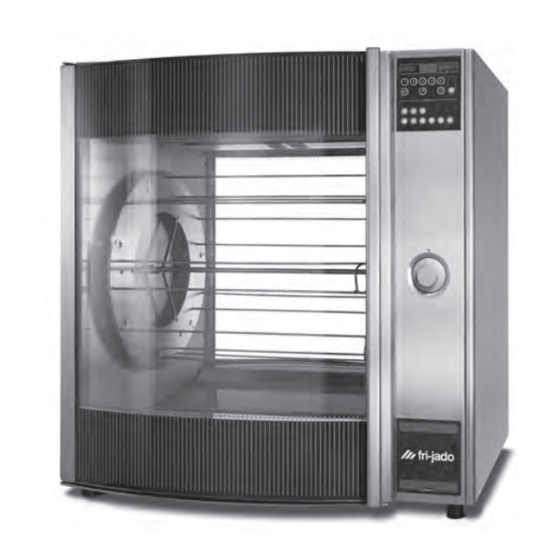
STG - ROTISSERIE OVEN MODELS
STW - WARMER MODELS
MODELS
Programmable controls
Warmers
* Fri-Jado produced Programmable Rotisseries and Warmers with serial numbers starting with 1000
WWW.FRIJADO.COM
FRI-JADO FJ 1000
FJ1000*
This manual is prepared for the use of trained Service Technici-
ans and should not be used by those not properly qualified. If
you have attended training for this product, you may be quali-
fied to perform all the procedures in this manual.
This manual is not intended to be all encompassing. If you have
not attended training for this product, you should read, in its
entirety, the repair procedure you wish to perform to determine
if you have the necessary tools, instruments and skills required
to perform the procedure. Procedures for which you do not have
the necessary tools, instruments and skills should be performed
by a trained technician.
Reproduction or other use of this Manual, without the express
written consent of Fri-Jado, is prohibited.
STG5 P
STG7 P
STW 5
STW 7
- NOTICE -
Service Manual STG5/7 STW5/7 form 9123647 rev. 03/2014
USA
Advertisement
Table of Contents
Troubleshooting

Related Manuals for Fri-Jado FJ 1000


Summary of Contents for Fri-Jado FJ 1000
- Page 1 Warmers STW 5 STW 7 * Fri-Jado produced Programmable Rotisseries and Warmers with serial numbers starting with 1000 - NOTICE - This manual is prepared for the use of trained Service Technici- ans and should not be used by those not properly qualified. If you have attended training for this product, you may be quali- fied to perform all the procedures in this manual.
- Page 2 PAGE Page 2 Service Manual STG5/7 STW5/7 form 9123647 rev. 03/2014...
-
Page 3: Service Manual Stg5/7 Stw5/7 Form 9123647 Rev
TABLE OF CONTENTS Versions Version Issue date Remarks dd/mm/yy 01/2012 05/01/2012 Switch, castors and electric diagrams adjusted. 03/2014 01/03/2014 Textual changes. Troubleshooting adapted. Exploded views modified. Service Manual STG5/7 STW5/7 form 9123647 rev. 03/2014 Page 3... -
Page 4: Table Of Contents
INDEX Index ................................4 General technical data ..........................6 Technical Data U.S. Standard Models ....................6 Technical Data U.S. Special Models ....................... 6 Programming instructions for the STG5 / STG7 and STW5 / STW7 ............7 Optional settings for the STG5 and STG7 ....................9 Removal and replacement of parts for the STG5 and STG7 .............. - Page 5 TABLE OF CONTENTS General troubleshooting list ........................29 Troubleshooting the STG 5/7 Rotisseries .................... 29 Troubleshooting the STW 5/7 warmers ....................30 Analytic troubleshooting list ......................... 31 Servicing and repairing of the rotisseries STG 5/7P ................31 Servicing and repairing of the Warmers STW 5/7 ................35 Exploded views &...
-
Page 6: General Technical Data
GENERAL TECHNICAL DATA GENERAL TECHNICAL DATA This manual covers the STG series rotisserie ovens and the STW series warmers starting with serial number #1000 (called FJ1000 from here). Ovens and warming cabinets come in two sizes. Ovens and cabinets will also be delivered in stacked versions. • STG 5 – Oven with 5 spits ( 15 to 20 chickens ) or 5 baskets ( 15 chickens ). -
Page 7: Programming Instructions For The Stg5 / Stg7 And Stw5 / Stw7
PROGRAMMING INSTRUCTIONS PROGRAMMING INSTRUCTIONS FOR THE STG5 / STG7 AND STW5 / STW7 DISPLAY AND KEYS Time Display 8 8 8 4 1 0 8 8 8 8 0 0 3 0 Temperature Display Temperature hold indicator Second step indicator Program indicators First step indicator Program keys... - Page 8 PROGRAMMING INSTRUCTIONS SETTING ACTUAL TIME 15 PROGRAMS Press and hold Time of After the unit is swit- day key ched-on the time display 8888 1040 88 8 p 01 88 88 15 p r indicates: 15PR Press Up or Down key Key 1: Release Time of day key 1x = program 01...
-
Page 9: Optional Settings For The Stg5 And Stg7
PROGRAMMING INSTRUCTIONS SECOND COOKING STEP (TEMPERATURE) TEMPERATURE HOLD Press and hold Tempera- Press Temperature Hold ture key process key 8 8 8 1 8 5 8 88 8 0 00 0 8888 0030 Press Up or Down key Temperature Hold sym- bol lights up Press and hold the Tem- perature key... - Page 10 PROGRAMMING INSTRUCTIONS SET PROGRAM END TIME DISPLAY SET TIME & TEMPERATURE Select a pre-defined Select a pre-defined program program 8888 1030 8 8 8 4 1 0 8 8 88 0 0 40 Press and hold the Pro- Press Cooking, Grilling gram end key or Temperature hold key Press Up key...
-
Page 11: Removal And Replacement Of Parts For The Stg5 And Stg7
REMOVAL AND REPLACEMENT OF PARTS REMOVAL AND REPLACEMENT OF PARTS FOR THE STG5 AND STG7 WARNING: Disconnect the electrical power to the machine at the main circuit box. Place a tag on the circuit box indicating the circuit is being serviced. RIGHT OR LEFT SIDE PANEL 1. -
Page 12: Knob
REMOVAL AND REPLACEMENT OF PARTS KNOB 1. Remove cover plate on the knob with a small screw driver. 2. Loosen the srew inside the knob. 3. Remove the knob with ring. 4. Reverse the procedure to install. Note: check that the ring behind the knob is in the right position and runs free from the panel. -
Page 13: Electric Panel
REMOVAL AND REPLACEMENT OF PARTS ELECTRIC PANEL 1. Remove the operating panel according prior procedure. 2. Remove on the front side the screws that secure the panel. 3. Remove on the inside bottom of the elec- tric panel the bolt and nuts. 4. -
Page 14: Panel And Keypad Assembly
REMOVAL AND REPLACEMENT OF PARTS PANEL AND KEYPAD ASSEMBLY 1. Remove the operating panel according prior procedure. 2. Remove the display according prior proce- dure. 3. Remove the nuts that secure the keypad and remove the keypad. 4. Reverse the procedure to install. NAMEPANEL 1. -
Page 15: Quartz Lamp
REMOVAL AND REPLACEMENT OF PARTS QUARTZ LAMP Caution: Do not touch the glass with your hands. The moisture from your hands could affect the live span of the lamp. This moisture can be remo- ved with alcohol while the lamp is cold. Note: Use a clean rag or paper towel to replace the lamp. -
Page 16: High Limit Thermostat
REMOVAL AND REPLACEMENT OF PARTS HIGH LIMIT THERMOSTAT 1. Remove the right side panel according prior procedure. 2. Remove the suction and fan plate on the cei- ling on the inside of the oven. STG5 3. (STG 5 only) Remove the nut on the clamp (see black arrow) and slide clamp towards yourself. -
Page 17: Heating Element
REMOVAL AND REPLACEMENT OF PARTS HEATING ELEMENT 1. Remove the rotor discs, right side panel, suction and fan plate on the ceiling accor- ding prior procedures. 2. Disconnect the wiring from the element. STG7 3. Remove the mounting nut. 4. Remove the element from the mounting clip and pull it from the wall. -
Page 18: Blower Motor Bottom Rotisserie (Stacked Stg)
REMOVAL AND REPLACEMENT OF PARTS BLOWER MOTOR BOTTOM ROTISSERIE (STACKED STG) 1. Remove the right side panel according prior procedures. 2. Remove the rotor discs, suction and fan plate on the ceiling inside the bottom oven. 3. Remove the wing nut on the fan blade and remove the fan blade. -
Page 19: Drive Motor
REMOVAL AND REPLACEMENT OF PARTS DRIVE MOTOR 1. Remove the right side panel and rotor discs according prior procedure. 2. Disconnect the wiring of the motor. Check where the wire, marked A is connected. 3. Remove the screws that secure the fan cover and remove the cover. -
Page 20: Door Adjustment (Left Side)
REMOVAL AND REPLACEMENT OF PARTS DOOR ADJUSTMENT (LEFT SIDE) 1. Remove the left side panel according prior procedure. 2. Loosen the nuts (A) of the upper hinge. The door must be closed. 3. Loosen the locknut (B) and adjust the bolt (C) in or out to adjust the door. -
Page 21: Door Outside
REMOVAL AND REPLACEMENT OF PARTS DOOR OUTSIDE 1. Lift the inner door out of the hinges and lay this aside. 2. Remove the left side panel according prior procedure. 3. Remove the 2 nuts behind the upper hinge and loosen the locknut according prior pro- cedure. -
Page 22: Removal And Replacement Of Parts For The Stw 5 And Stw 7
REMOVAL AND REPLACEMENT OF PARTS REMOVAL AND REPLACEMENT OF PARTS FOR THE STW 5 AND STW 7 WARNING: Disconnect the electrical power to the machine at the main circuit box. Place a tag on the circuit box indicating the circuit is being serviced. BLOWER MOTOR 1. -
Page 23: Thermostat
REMOVAL AND REPLACEMENT OF PARTS THERMOSTAT 1. Remove the right side panel and the fan plate according prior procedures. 2. Remove the thermostat probe from the clamp inside the cavity (see arrow) and guide it outside through the opening. 3. Disconnect the wiring from the thermostat. 4. -
Page 24: Heating Element
REMOVAL AND REPLACEMENT OF PARTS HEATING ELEMENT 1. Remove the right side panel, racks, bottom plate and the fan plate according prior pro- cedures. 2. Disconnect the wiring from the element. 3. Remove the nuts and rings that secure the element and remove the element. -
Page 25: Electrical Tests And Service Procedures
ELECTRICAL TEST AND SERVICE PROCEDURES ELECTRICAL TESTS AND SERVICE PROCEDURES WARNING: Disconnect the electrical power to the machine at the main circuit box. Place a tag on the circuit box indicating the circuit is being serviced. HEATING ELEMENT TEST Type Wattage/Vol- Resistance Ω... -
Page 26: Pt500 Sensor Test
ELECTRICAL TEST AND SERVICE PROCEDURES PT500 SENSOR TEST Note: When testing the resistance of the sensor Temperature Ω Resistance remove the wiring. Refer to the removal and °F °C ± 5 Ohms replacement part of the manual on how to do this. -
Page 27: Keypad Test
ELECTRICAL TEST AND SERVICE PROCEDURES KEYPAD TEST 1. Remove the instrument panel according prior procedure. 2. Remove the display according prior proce- dure. 3. Remove the nuts that secure the panel with foil and remove panel. 4. Use a multimeter to test. Connect the measuring pins to the cable plug pins for each key to be tested as indicated in the dia- gram. -
Page 28: Control Location
ELECTRICAL TEST AND SERVICE PROCEDURES CONTROL LOCATION THERMOMETER THERMOSTAT DIAL Service Manual STG5/7 STW5/7 form 9123647 rev. 03/2014 Page 28... -
Page 29: General Troubleshooting List
TROUBLESHOOTING GENERAL TROUBLESHOOTING LIST TROUBLESHOOTING THE STG 5/7 ROTISSERIES Symptom Possible causes No power to oven controls. 1. Main breaker open. 2. Fuse F1 burned. 3. Main switch malfunction 4. Wiring loose. Main fuse or breaker blows. 1. Wiring incorrectly. 2. -
Page 30: Troubleshooting The Stw 5/7 Warmers
TROUBLESHOOTING TROUBLESHOOTING THE STW 5/7 WARMERS Symptom Possible causes No power to warmer controls. 1. Main breaker open. 2. Main switch malfunction. 3. Wiring loose. Main fuse or breaker blows. 1. Wiring incorrectly. 2. Heating element or blower shorted. 3. Wiring shorted. Blower motor does not run. -
Page 31: Analytic Troubleshooting List
TROUBLESHOOTING ANALYTIC TROUBLESHOOTING LIST SERVICING AND REPAIRING OF THE ROTISSERIES STG 5/7P This is an analytic description for servicing and repairing all major parts of the rotisseries and warmers. It consists off 4 basic steps to recognize and solve the problems. These steps are: 1. - Page 32 TROUBLESHOOTING Description of part Symptoms Possible causes Solving: checking/action PT-sensor Temperature indication on No connection Check the wiring. display runs up very fast between wires. Check thin wire on sensor. and over the maximum of 250°C / 482°F 290°C / 550°F in 20 se- conds) Temperature indication on Full contact bet-...
- Page 33 TROUBLESHOOTING Description of part Symptoms Possible causes Solving: checking/action Keypad on display No possibility to make a Permanent contact Check key functions. program of one, or more, Check functions of keypad. See table on membrane keys. page 24. Some keys don’t Check grey flat cable connection.
- Page 34 TROUBLESHOOTING Description of part Symptoms Possible causes Solving: checking/action Drive motor Motor doesn’t run Wiring. Check the wiring. Check the power to the motor. Coil malfunction Check resistance of the coils. See table on page 25. Between whiteA and white wire 234Ω Between whiteA and brown wire 117Ω...
-
Page 35: Servicing And Repairing Of The Warmers Stw 5/7
TROUBLESHOOTING SERVICING AND REPAIRING OF THE WARMERS STW 5/7 Description of part Symptoms Possible causes Solving: checking/action Heating element Warmer doesn’t reach Wiring. Check the wiring. adjusted temperature Check the power on the element. Element malfunc- Check the current with AC current tester. tion. -
Page 36: Exploded Views & Partlists
EXPLODED VIEWS AND PARTLISTS EXPLODED VIEWS & PARTLISTS STG 5 P - SHEET IRON WORK D-0093-01 Page 36 Service Manual STG5/7 STW5/7 form 9123647 rev. 03/2014... - Page 37 EXPLODED VIEWS AND PARTLISTS Item Part number Qty. Description Frame, ass. 9171125 Leg, rubber 1 15/16” 9011260 Leg, rubber 1 9/16”(till 01-01-2008) 9170428 Side panel, left 9170532 Side panel, right 4288322 Screw M5 x 10, SS socket button head 9123467 Indication plate 9174060 Cap, top...
-
Page 38: Stg 5 P - Components
EXPLODED VIEWS AND PARTLISTS STG 5 P - COMPONENTS 48-1 48-2 40-1 40-2 40-1-1 64-5 64-4 64-3 64-2 64-1 52-6 52-8 52-2 52-12 52-5 52-10 52-7 52-4 52-9 52-3 52-1 52-11 D-0093-02 Page 38 Service Manual STG5/7 STW5/7 form 9123647 rev. 03/2014... - Page 39 Heating element 208 V, 2000 9070094 Temperature sensor PT 500 9151010 Connecting block 9110023 Lamp holder, cap + housing 9172040 Name plate Fri-Jado, foil + 9056082 Quartz light, 1000 W backplate 9116662 Protection, lamp 9173017 Main power knob assembly 9140027...
-
Page 40: Stg 5 P - Doors
EXPLODED VIEWS AND PARTLISTS STG 5 P - DOORS 81-6 81-7 81-8 81-4 82-3 81-9 82-4 82-5 81-3 81-2 82-1 80-6 80-4 80-8 80-7 80-9 81-5 82-2 81-1 81.C 80-3 80-2 80-5 80-1 80.S 81-19 81-7 81-18 81-20 81-12 81-13 82-3 81-14 80-10... - Page 41 EXPLODED VIEWS AND PARTLISTS Item Part number Qty. Description Item Part number Qty. Description 80.S 9179859S Door service side, ass. 80-1 9170441 Hinge profile 9179855S Door inside, ass. 80-2 4288321 Screw M5 x 16, SS socket but- 82-1 9170442 Hinge profile ton head 82-2 0211520...
-
Page 42: Stg 7 P - Sheet Iron Work
EXPLODED VIEWS AND PARTLISTS STG 7 P - SHEET IRON WORK D-0095-01 Page 42 Service Manual STG5/7 STW5/7 form 9123647 rev. 03/2014... - Page 43 EXPLODED VIEWS AND PARTLISTS Item Part number Qty. Description ..Frame, ass. 9171125 Leg, rubber 1 15/16” 9011260 Leg, rubber 1 9/16”(till 01-01-2008) 9170419 Side panel, left 9170531 Side panel, right 4288322 Screw M5 x 10, SS socket button head 9123467 Indication plate 9174099...
-
Page 44: Stg 7 P - Components
EXPLODED VIEWS AND PARTLISTS STG 7 P - COMPONENTS Page 44 Service Manual STG5/7 STW5/7 form 9123647 rev. 03/2014... - Page 45 Heating element 208 V, 2100 9070094 Temperature sensor 9151010 Connecting block 9110909 Heating element 208 V, 3100 9172040 Name plate Fri-jado, foil + backplate 9110023 Lamp holder, cap + housing 9173017 Main power knob assembly 9056082 Quartz light, 1000 W...
-
Page 46: Stg 7 P - Doors
EXPLODED VIEWS AND PARTLISTS STG 7 P - DOORS 81-6 81-7 81-8 81-4 81-9 82-3 82-4 82-5 81-3 81-2 82-1 80-6 80-4 80-8 80-7 80-9 81-5 82-2 81-1 81.C 80-3 80-2 80-5 80-1 80.S 81-19 81-7 81-18 81-20 81-12 81-13 82-3 81-14 80-10... - Page 47 EXPLODED VIEWS AND PARTLISTS Item Part number Qty. Description Item Part number Qty. Description 80.S 9179850S Door service side, ass. 81-20 4311110 Washer 80-1 9170422 Hinge profile 80-2 4288321 Screw M5 x 16, SS 9179852 Door inside, ass. socket button head 82-1 9170423 Hinge profile...
-
Page 48: Stw 5 - Sheet Iron Work
EXPLODED VIEWS AND PARTLISTS STW 5 - SHEET IRON WORK STW 5 USA D-0169-01 Page 48 Service Manual STG5/7 STW5/7 form 9123647 rev. 03/2014... - Page 49 EXPLODED VIEWS AND PARTLISTS Item Part number Qty. Description ..Frame, ass. 9170428 Side panel, left 9170480 Side panel, right 9123492 Indication plate 4288322 Screw M5 x 10, SS socket button head 9174060 Cap, top 9170432 Side panel, top 9174092 Reinforcement, side plate, right 9174061 Cover, removable...
-
Page 50: Stw 5 - Components
EXPLODED VIEWS AND PARTLISTS STW 5 - COMPONENTS 45-5 45-7 45-6 45-8 45-4 45-3 45-2 44-5 44-7 44-6 44-8 44-4 45.C 45-1 44-3 44-2 44-1 44-4 45-18 45-17 45-6 45-19 45-11 45-12 44.S 45-13 50-1 50-2 44-6 44-9 44-10 44-16 44-11 44-12 44-6... - Page 51 Mounting profile, hinge side 9172400 Connecting cable with plug 44-6 3702342 Flange bush, PTFE 3 mm 6-15P 44-7 4311110 Washer 9172040 Name plate Fri-jado, foil + backplate 44-8 0144359 Nut, self locking M5 9173056 Main power/thermostat knob 44-9 4288320 Screw M5x45 SS assembly...
-
Page 52: Stw 7 - Sheet Iron Work
EXPLODED VIEWS AND PARTLISTS STW 7 - SHEET IRON WORK STW 7 USA D-0170-01 Page 52 Service Manual STG5/7 STW5/7 form 9123647 rev. 03/2014... - Page 53 EXPLODED VIEWS AND PARTLISTS Item Part number Description ..Frame 9170419 Side panel, left 9170479 Side panel, right 9123467 Indication plate 4288322 Screw M5 x 10, SS socket button head 9174045 Cap, top 9170421 Side panel, top 9174046 Reinforcement, side plate, right 9174005 Cover, removable 9174048...
-
Page 54: Stw 7 - Components
EXPLODED VIEWS AND PARTLISTS STW 7 - COMPONENTS 45-5 45-7 45-6 45-8 45-4 45-3 44-5 44-7 44-6 45-2 44-8 44-4 45.C 44-3 44-2 45-1 44-1 44-4 45-18 45-17 45-6 45-19 45-11 45-12 44.S 45-13 50-1 50-2 44-6 44-9 44-10 44-16 44-11 44-12 44-6... - Page 55 Mounting profile, hinge side 9172403 Connecting cable with plug 15- 44-6 3702342 Flange bush, PTFE 3 mm 44-7 4311110 Washer 9172040 Name plate Fri-jado, foil + back- plate 44-8 0144359 Nut, self locking M5 9173056 Main power/thermostat knob 44-9 4288320 Screw M5x45 SS...
-
Page 56: Electrical Diagrams
ELECTRICAL DIAGRAMS ELECTRICAL DIAGRAMS STG 5 P CIRCUIT DIAGRAM Service Manual STG5/7 STW5/7 form 9123647 rev. 03/2014 Page 56... -
Page 57: Stg 5 P Wiring Diagram
ELECTRICAL DIAGRAMS STG 5 P WIRING DIAGRAM Page 57 Service Manual STG5/7 STW5/7 form 9123647 rev. 03/2014... -
Page 58: Stg 5 P Wiring Diagram (Till Serial Number 100050804)
ELECTRICAL DIAGRAMS STG 5 P WIRING DIAGRAM (TILL SERIAL NUMBER 100050804) Service Manual STG5/7 STW5/7 form 9123647 rev. 03/2014 Page 58... -
Page 59: Stg 7 P Circuit Diagram
ELECTRICAL DIAGRAMS STG 7 P CIRCUIT DIAGRAM Page 59 Service Manual STG5/7 STW5/7 form 9123647 rev. 03/2014... -
Page 60: Stg 7 P Wiring Diagram
ELECTRICAL DIAGRAMS STG 7 P WIRING DIAGRAM Service Manual STG5/7 STW5/7 form 9123647 rev. 03/2014 Page 60... -
Page 61: Stg 7 P Wiring Diagram (Till Serial Number 100050804)
ELECTRICAL DIAGRAMS STG 7 P WIRING DIAGRAM (TILL SERIAL NUMBER 100050804) Page 61 Service Manual STG5/7 STW5/7 form 9123647 rev. 03/2014... -
Page 62: Stw 5 Circuit Diagram
ELECTRICAL DIAGRAMS STW 5 CIRCUIT DIAGRAM Service Manual STG5/7 STW5/7 form 9123647 rev. 03/2014 Page 62... -
Page 63: Stw 5 Wiring Diagram
ELECTRICAL DIAGRAMS STW 5 WIRING DIAGRAM Page 63 Service Manual STG5/7 STW5/7 form 9123647 rev. 03/2014... -
Page 64: Stw 7 Circuit Diagram
ELECTRICAL DIAGRAMS STW 7 CIRCUIT DIAGRAM Service Manual STG5/7 STW5/7 form 9123647 rev. 03/2014 Page 64... -
Page 65: Stw 7 Wiring Diagram
ELECTRICAL DIAGRAMS STW 7 WIRING DIAGRAM Page 65 Service Manual STG5/7 STW5/7 form 9123647 rev. 03/2014... - Page 66 Service Manual STG5/7 STW5/7 form 9123647 rev. 03/2014 Page 66...
- Page 67 Service Manual STG5/7 STW5/7 form 9123647 rev. 03/2014 Page 67...
- Page 68 For technical support call: 877 374-5236 For parts call: 877 392-7851 Fri-Jado Inc. •1401 Davey Road • Sweet 100 • Woodridge, IL. 60517 • USA • tel. 630-630-7950 • fax 630-689-11424 • toll free 877-FRI-JADO • us.info@frijado.com • www.frijado.com...
Need help?
Do you have a question about the FJ 1000 and is the answer not in the manual?
Questions and answers