Table of Contents
Advertisement
Advertisement
Table of Contents

Related Manuals for Inspur NE5260M5


Summary of Contents for Inspur NE5260M5
- Page 1 Inspur Server User Manual NE5260M5...
- Page 2 Inspur. The information in this manual is subject to change without notice. Inspur is the registered trademark of Inspur. All the other trademarks or registered trademarks mentioned in this manual are the property of their respective holders.
- Page 3 After the first login, please change the BMC user password in time. 4. Please install the product-compatible operating system and use the driver provided by Inspur. If you use an incompatible operating system or non-Inspur driver, it may cause compatibility issues and affect the normal use of the product, Inspur will not assume any responsibility or liability.
-
Page 4: Table Of Contents
Contents 1 Safety Instructions ......................... 1 2 Product Specifications ........................6 2.1 Introduction ..........................6 2.2 Features and Specifications ......................7 3 Component Identification ......................9 3.1 Front/Rear Panel Components ....................9 3.2 Motherboard Components......................10 4 Operations ............................. 12 4.1 Power up the Server ........................ - Page 5 6.3 Memory Option .......................... 23 6.4 Hot-plug HDDOption ........................26 6.5 Air Baffle Option ......................... 27 7 Cabling ............................28 8 BIOS Setup ............................. 31 8.1 Common Operations ........................31 8.2 BIOS Parameter Description ....................... 48 8.3 Firmware Update ........................87 9 BMC Settings ..........................
- Page 6 12.4 European Union Regulatory Notice ..................125 12.5 Disposal of Waste Equipment by Users in the European Union ..........125 12.6 Chinese Notice.......................... 126 12.7 Battery Replacement Notice ....................126 13 Electrostatic Discharge ........................ 127 13.1 Preventing Electrostatic Discharge ................... 127 13.2 Grounding Methods to Prevent Electrostatic Discharge ............
-
Page 7: Safety Instructions
For your safety, please do not attempt to remove the cover of the system to remove or replace any component without assistance provided by Inspur. Only service technicians trained by Inspur are authorized to remove the cover of the host, and to remove and replace internal components. - Page 8 The following considerations may help avoid the occurrence of problems that could damage the components or cause data loss, etc. In the event of the following, please unplug the power cable plug from the power socket and contact Inspur’s customer service department:...
- Page 9 Close the host cover, reconnect the system to the power socket, and then power In case of operation failure or other abnormal situations, please contact Inspur and get technical support.
- Page 10 Upon receiving the proper authorization from Inspur and dismounting the internal components, please pay attention to the followings: Switch the system power supply off and disconnect the cables, including all connections of the system.
- Page 11 Safety Instructions Do not overload the AC power supply branch circuits in the rack. The total load of the rack should not exceed 80% of the ratings of the branch circuits. Ensure that components in the rack have good ventilation conditions. When repairing components in the rack, never step on any other components.
-
Page 12: Product Specifications
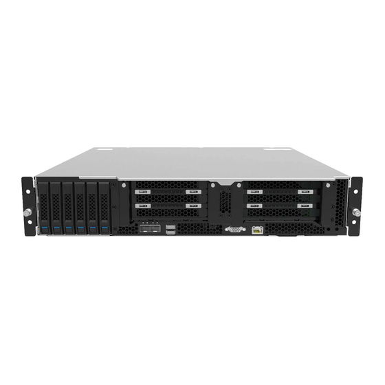
2 Product Specifications 2.1 Introduction Inspur Server NE5260M5 is a new generation of 2U dual-socket edge server. It is designed on the basis of a new generation of Intel® Xeon® scalable processors to provide excellent computing performance. It features the compact design, wide operating temperature range and high reliability, meeting OTII standards. -
Page 13: Features And Specifications
Product Specifications 2.2 Features and Specifications Processor Supports a new generation of Skylake & Cascadelake Intel® Xeon® scalable Processor Type processors, and supports up to TDP205W Memory Supports up to 16 DIMMs, supports 2400/2666/2933 RDIMM and LRDIMM Memory Type memories, and supports up to 4 AEP memories Memory Slot Qty. - Page 14 2 onboard PCI Express 3.0 x32 slots, used to support PCI-E Riser cards. The Riser card supports horizontal-inserted full-height cards. Full configuration 1: One Riser card can be installed into the Riser slot1 (CPU0). Supports 1 PCI Express 3.0 x16 slot (top slot, FHFL card) + 1 PCI Express 3.0 x16 slot (middle slot, x8 lanes, FHHL card) + 1 PCI Express3.0 x8 slot (bottom slot, FHHL card).
-
Page 15: Component Identification
Component Identification 3 Component Identification 3.1 Front/Rear Panel Components Item Description HDD modules PCIE slots (0-2) PCIE slots (3-5) USB3.0/2.0 Onboard 10GbE ports VGA serial port BMC management port System status LED Power LED/button UID LED/button System fan 3 System fan 2 System fan 1 System fan 0 PSU0... -
Page 16: Motherboard Components
Drive Tray LEDs Item Description Status & Interpretation Steady green: Normal Activity status LED Flashing green: Read and write activity Steady red: A failure occurs Fault alarm LED Steady blue: Drive positioning Flashing pink: RAID rebuilding 3.2 Motherboard Components Item Description DIMM slots (CPU0) - Page 17 Component Identification Item Description CPU1 socket GPU power connector 1 System fan connector 3 DIMM slots (CPU1) Internal DB9 serial port CPLD JTAG cable connector UID LED/button Power LED/button PCIE1_CPU slot Battery slot PCIex8 cable connector (CPU1) UPLINKx8 cable connector (CPU1) BMC management port M.2 Riser slot VGA port...
-
Page 18: Operations
4 Operations 4.1 Power up the Server Insert the power cord plug, then press the Power Button. 4.2 Power down the Server WARNING: To reduce the risk of personal injury, electric shock, or damage to the equipment, remove the power cord to remove power from the server. The front panel Power Button does not completely shut off system power. -
Page 19: Remove The Access Panel
Operations 4.4 Remove the Access Panel WARNING: To reduce the risk of personal injury from hot surfaces, allow the drives and the internal system components to cool before touching them. CAUTION: For proper cooling, do not operate the server without the access panel, air baffle, or fan installed. -
Page 20: Install The Pcie Riser Cage
Power down the server. Extend the server from the rack. Remove the access panel. Remove the PCIE Riser cage. 4.7 Install the PCIE Riser Cage Power down the server. Extend the server from the rack. Remove the access panel. Install the PCIE Riser cage. Install the access panel. - Page 21 Operations Remove the access panel. Remove the air baffle.
-
Page 22: Setup
Leave a minimum clearance of 121.9 cm (48 in) from the back of the rack to the back of another rack or row of racks. Inspur Servers draw in cool air through the front door and expel warm air through the rear door. Therefore, the front and rear rack doors must be adequately ventilated to allow ambient room air to enter the cabinet, and the rear door must be adequately ventilated to allow the warm air to escape from the cabinet. - Page 23 Setup • Side—The clearance between the installed rack component and the side panels of the rack must be a minimum of 7 cm (2.75 in). 5.1.2 Temperature Requirements To ensure continued safe and reliable equipment operation, install or position the system in a well-ventilated, climate-controlled environment.
-
Page 24: Rack Warnings
Because of the high ground-leakage currents associated with multiple servers connected to the same power source, Inspur recommends the use of a PDU that is either permanently wired to the building’s branch circuit or includes a nondetachable cord that is wired to an industrial-style plug. -
Page 25: Identifying The Contents Of The Server Shipping Carton
Setup • The stabilizing feet are attached to the rack if it is a single-rack installation. • The racks are coupled together in multiple-rack installations. • Only one component is extended at a time. A rack may become unstable if more than one component is extended for any reason. -
Page 26: Installing The Operating System
5.6 Installing the Operating System To operate properly, the server must have a supported operating system installed. For the latest information on supported operating systems, refer to the Inspur website (http://www. inspur.com). To install the operating system on the server, you can download from the official website... -
Page 27: Hardware Options Installation
Hardware Options Installation 6 Hardware Options Installation 6.1 Introduction If more than one option is being installed, read the installation instructions for all the hardware options and identify similar steps to streamline the installation process. WARNING: To reduce the risk of personal injury from hot surfaces, allow the drives and the internal system components to cool before touching them. - Page 28 Remove the air baffle. Remove the heatsink. Install the processor: Step 1: Align the Clip’s triangle mark with the CPU’s corner mark, and then assemble the Clip and CPU together. Step 2: Align the heatsink position marked by “1” with the Clip’s triangle mark, vertically align the mounting holes on the heatsink with those on the Clip, and assemble the heatsink and Clip together.
-
Page 29: Memory Option
Hardware Options Installation Step 3: Install the assembled heatsink module onto the CPU socket, and the position marked by “1” should be aligned with the triangle mark on the CPU socket. Tighten the screws according to the sequence of 1, 2, 3, 4. Notes: ●... - Page 30 ● DIMM population guidelines: Only DIMMs of the same type could be used in the same machine. Detailed DIMM population and combination principles are as follows: One-CPU, install the DIMMs according to the following table: DIMM Qty. & Location DIMM Slots Supported by Each CPU CPU0_C0D0 ●...
- Page 31 Hardware Options Installation DIMM Qty. & Location DIMM Slots Supported by Each CPU CPU0_C0D0 ● ● ● ● ● ● ● ● ● CPU0_C0D1 ● ● CPU0_C1D0 ● ● ● ● ● ● DIMM Slots CPU0_C2D0 ● ● ● ● ●...
-
Page 32: Hot-Plug Hddoption
6.4 Hot-plug HDD Option CAUTION: For proper cooling, do not operate the server without the access panel, baffles, expansion slot covers, or blanks installed. If the server supports hot-plug components, minimize the amount of time the access panel is open. Check the status of the hard disk drive from the hot-plug HDD LED. -
Page 33: Air Baffle Option
Hardware Options Installation Step 3: Use four screws to fix the drive into the tray. Step 4: Install the drive tray into the chassis, and lock the lever firmly. 6.5 Air Baffle Option CAUTION: For proper cooling, do not operate the server without the access panel, baffles, expansion slot covers, or blanks installed. -
Page 34: Cabling
7 Cabling Data cables of the power board Data cables of the drive backplane 6NVME... - Page 35 Cabling 6SATA 4NVME...
- Page 36 4NVME+2SATA 2NVME+4SATA...
-
Page 37: Bios Setup
Power on the server. The system will then start to boot. When the following content appears below Inspur logo on the screen: “Press <DEL> to SETUP or <TAB> to POST or <F11> to Boot Menu or <F12> to PXE Boot.” Press DEL key. When “Entering Setup …” appears in the lower right corner of the screen, it will enter the BIOS setup soon. - Page 38 • Press F11 to enter the boot management interface, select the boot device. • Press F12 to boot the PXE. BIOS Setup Interface Control Key Instruction Table Function <Esc> Exit or return from submenu to main menu <←> or <→> Select a menu <↑>...
- Page 39 Network, Storage, Video OPROM Policy and Other PCI devices, as shown in the following figure. At present, Inspur Purley platform servers are set to UEFI Mode by default. Compared with Legacy mode, UEFI mode has many advantages: It supports boot from the GPT disk which is larger than 2.2T, supports IPv6/IPv4 PXE boot, and provides UEFI Shell environment.
- Page 40 8.1.4 View CPU Information Login to the BIOS interface, select “Processor -> Processor Configuration -> Processor Information”, and press Enter to display the CPU detailed information, as shown in the following figure. 8.1.5 View Memory Information Login to the BIOS interface, select “Processor -> Memory Configuration -> Memory Topology”, and press Enter to display the manufacturer, speed, capacity and other...
- Page 41 BIOS Setup information of the memories in position, as shown in the following figure. 8.1.6 View HDD Information and RAID Configuration 8.1.6.1 View HDD Information Login to the BIOS interface, select “Chipset -> PCH SATA Configuration/PCH sSATA Configuration”, and press Enter to display the HDD information of the current onboard SATA ports or sSATA ports, as shown in the following figures.
- Page 42 8.1.6.2 RAID Mode Settings Set the SATA Mode Option to [RAID], press F10 to save the setting, and the system reboots. When Boot Mode is set to UEFI mode, in the BIOS Setup Advanced interface, there will be the Intel(R) RSTe SATA Controller menu, as shown in the following figure. Press Enter, the executable operation and the current disk information will be displayed, as shown in the following figure.
- Page 43 BIOS Setup Create RAID volume. Select Create RAID Volume option, and press Enter, as shown in the following figure. Create RAID Menu Instruction Table Interface Function Description Parameters Please enter a volume name less than 16 characters without containing any special Name characters.
- Page 44 Select disks to make RAID volume, press Enter, select X, and then press Enter to return to Select Disks Create RAID Volume interface. Strip Size Please select the strip size, only RAID0 and RAID5 volumes could enable this option. Set the volume capacity, and the maximum capacity is shown in the Help information on Capacity the right side.
- Page 45 BIOS Setup When Boot Mode is set to Legacy, a prompt “Press <CTRL-I> to enter Configuration Utility…” will appear on the screen during system booting. Press [Ctrl] and [I] keys at the same time to enter SATA RAID configuration, as shown in the following figure. After entering SATA RAID configuration interface, it will display the main menu list, the information (disk ID, disk type, disk capacity, volume member or not) of disks connected to SATA controller, and the existed RAID volumes information (including volume ID, name, RAID...
- Page 46 Key Instruction Table Description ↑↓ Used to move cursor in different menus or to change values of menu options To select the next menu option Enter To select a menu To exit menu or return to previous menu from sub-menu Menu Instruction Table Create RAID Volume To create an RAID volume...
- Page 47 BIOS Setup Create RAID Menu Instruction Table Interface Parameters Function Description Please enter a volume label name less than 16 characters without containing any Name special characters. Please select RAID volume level. If no volume has been created at present, there are four volume levels of RAID0 (Stripe), RAID1 (Mirror), RAID10 (RAID0+1) and RAID5 (Parity) for selection.
- Page 48 Reset Disks to Non-RAID menu. After entering Reset Disks to Non-RAID menu, system will display all disks in RAID volume. Please use the space key to select the disk to reset according to the actual demand, and then press Enter to reset the disk. The system will prompt “Are you sure you want to reset RAID data on selected disks? (Y/N)”...
- Page 49 BIOS Setup configuration interface, as shown in the following figure. The system will prompt “Are you sure you want to exit? (Y/N)”, enter “Y” to exit, or enter “N” to cancel the exit operation. 8.1.7 View and Set BMC Network Parameters 8.1.7.1 View BMC Network Parameters Login to the BIOS interface, select “Server Mgmt ->...
- Page 50 8.1.7.2 BMC Network Settings Take BMC Sharelink port as an example to introduce the settings of BMC IPv4 network parameters, as shown in the following table. BMC Network Configuration Instruction Table Interface Parameters Function Description Default Value Set the way to get BMC network parameters, options include: Get BMC Sharelink /Dedicated Do Nothing...
- Page 51 BIOS Setup will prompt “Set Static BMC IP Address Source Success!!”, as shown in the following figure. Select the Station IP Address option. Press Enter, the Station IP Address window pops up. Input the Static IP manually. After the setting is completed, press Enter to confirm, as shown in the following figures: If the setting succeeds, the system prompts “Set Static BMC Station IP OK!!!”...
- Page 52 confirm, and the IP will take effect immediately. If the setting fails, the system prompts “Set Static BMC Station IP Fail!!!” If the IP does not change, the system prompts “Static BMC Station IP Not Change!!!” If the input IP is invalid, the system prompts “Invalid Station IP Entered!!!”, and assign 0.0.0.0 to the IP address.
- Page 53 BIOS Setup After the dynamic network takes effect, the system will prompt “Get Dynamic BMC Dhcp Success!!”, and the interface will be shown as the following figure. Note: Please make sure that the BMC management port is connected to the network when you use the Manual setting options.
-
Page 54: Bios Parameter Description
8.2 BIOS Parameter Description 8.2.1 Main Main interface displays the basic information of BIOS system, including BIOS/BMC/ME version, CPU type, total memory capacity and system time. Main Interface Instruction Table Interface Parameters Function Description Product Name Product name Serial Number Serial number Customer ID Customer ID... - Page 55 BIOS Setup 8.2.2 Advanced Advanced interface includes the BIOS system parameters and related function settings, such as ACPI, serial port, PCI subsystem, CSM, USB, onboard NIC and so on. Advanced Interface Instruction Table Interface Parameters Function Description Trusted Computing Trusted computing configuration Super IO Configuration AST2500 I/O chip parameter configuration Serial Port Console Redirection...
- Page 56 Trusted Computing Interface Instruction Table Interface Parameters Function Description Default Value Security device support settings. Options include: Enabled Disabled Security Device Support Enabled BIOS supports TPM TCG version 1.2/2.0. BIOS supports TPM module through TPM software binding, when the verification of software binding fails, BIOS will record the error to SEL.
- Page 57 BIOS Setup Super IO Configuration Interface Instruction Table Interface Parameters Function Description Serial port 0 configuration, the configuration interface provides this serial Serial Port 0 Configuration port’s on-off control and resource allocation control. Users can manually adjust the IO PORT and IRQ number that COM PORT uses. Serial Port 1 Configuration Serial port 1 configuration (virtual serial port) 8.2.2.2.1 Serial Port 0 Configuration Serial Port 0 Configuration interface is used to set the options related with serial port 0.
- Page 58 Serial Port Console Redirection Interface Instruction Table Interface Parameters Function Description Default Value Serial port console redirection on-off settings. Options include: Console Redirection Disabled Enabled Disabled Serial port console redirection parameter Console Redirection Settings ---- settings 8.2.2.4 Console Redirection Settings When the Console Redirection is set to [Enabled], the Console Redirection Settings menu will be opened.
- Page 59 BIOS Setup Console Redirection Settings Interface Instruction Table Interface Parameters Function Description Default Value Terminal type settings. Options include: VT100 Terminal Type VT100+ ANSI VT-UTF8 ANSI Baud rate settings. Options include: 9600 19200 Bits per second 115200 38400 57600 115200 Serial port data width settings.
- Page 60 8.2.2.5 PCI Subsystem Settings PCI Subsystem Settings interface is used to set the options related with PCI subsystem. PCI Subsystem Settings Interface Instruction Table Interface Parameters Function Description Default Value Above 4G memory access control on-off settings. Options include: Above 4G Decoding Enabled Enabled Disabled...
- Page 61 BIOS Setup Network Stack Configuration Interface Instruction Table Interface Parameters Function Description Default Value Network stack on-off settings. Options include: Enabled Network Stack Enabled Disabled Only this option is enabled, the following options can be displayed and the functions can be set. UEFI Ipv4 PXE support on-off settings.
- Page 62 CSM Configuration Interface Instruction Table Interface Parameters Function Description Default Value CSM support on-off settings. Options include: CSM Support Enabled Disabled Disabled A20 line control mode settings. Options include: Upon Request GateA20 Active Always Upon Request A20 is an address line, which controls the system how to access the memory space larger than 1MB.
- Page 63 BIOS Setup 8.2.3 Chipset Chipset interface includes the information settings and runtime error logging settings of PCH SATA/sSATA, USB and ME devices. Chipset Interface Instruction Table Interface Parameters Function Description PCH SATA Configuration PCH SATA configuration PCH sSATA Configuration PCH sSATA configuration USB Configuration USB configuration Miscellaneous Configuration...
- Page 64 PCH SATA Configuration Interface Instruction Table Interface Parameters Function Description Default Value SATA controller on-off settings. Options include: SATA Controller Enabled Enabled Disabled SATA mode settings. Options include: SATA Mode Options AHCI AHCI RAID SATA Port 0~7 SATA port 0~7 HDD information ---- SATA port on-off settings.
- Page 65 BIOS Setup PCH sSATA Configuration Interface Instruction Table is omitted here. 8.2.3.2 USB Configuration USB Configuration is used to set the options related with the onboard USB ports. USB Configuration Interface Instruction Table Interface Parameters Function Description Default Value Onboard USB port on-off settings. Options include: USB N Enabled Enabled...
- Page 66 Miscellaneous Configuration Interface Instruction Table Interface Parameters Function Description Default Value Power state settings when restoring on AC power loss. Options include: Restore AC Power Loss Power OFF Power OFF Last State Power ON The maximum page table size settings. Options include: Max Page Table Size For older OS, please select 2MB, otherwise, it may cause a problem.
- Page 67 BIOS Setup Recovery Cause Recovery cause PTT support on-off settings. Options include: PTT Support Enabled Disabled Disabled Altitude Altitude settings 8000 MCTP bus owner is located in PCIe: [15:8] bus, [7:3] MCTP Bus Owner device, [2:0] function. If set to 0, it means disabled. ME Firmware Features ME FW features ----...
- Page 68 Processor Interface Instruction Table Interface Parameters Function Description Processor Configuration Processor configuration Common Configuration Common configuration UPI Configuration UPI configuration Memory Configuration Memory configuration IIO Configuration IIO configuration Advanced Power Management Configuration Advanced power management configuration 8.2.4.1 Processor Configuration Processor Configuration interface is used to set the options related with the processor.
- Page 69 BIOS Setup Processor Configuration Interface Instruction Table Interface Parameters Function Description Default Value Processor information submenu, the processor’s detailed Processor Information ---- information CPU core settings. Input the number of CPU cores you want to enable. In the Help information, it will display the Active Cores effective values you can set and the maximum number of physical cores according to the current CPU usage.
- Page 70 DCU streamer prefetcher on-off settings. Options include: Enabled DCU Streamer Prefetcher Disabled Enabled This function can prefetch CPU data to shorten the data reading time. DCU IP prefectcher on-off settings. Options include: Enabled DCU IP Prefectcher Disabled Enabled This function can judge whether there is data to prefetch, to shorten the data reading time.
- Page 71 BIOS Setup Common Configuration Interface Instruction Table Interface Parameters Function Description Default Value MMIO high base settings. Options include: MMIO High Base MMIO high granularity size settings. Options include: MMIO High Granularity Size 256G 256G 1024G Numa on-off settings. Options include: Numa Enabled Enabled...
- Page 72 Link speed mode settings. Options include: Link Speed Mode Fast Fast Slow Link frequency select settings. Options include: Auto Link Frequency Select 9.6 GT/s Auto 10.4 GT/s Use Per Link Setting Link L0p on-off settings. Options include: Enabled Link L0p Enable Disabled Disabled Link power-saving mode setting, which is set when the bandwidth is...
- Page 73 BIOS Setup Memory Configuration Interface Instruction Table Interface Parameters Function Description Default Value Enforce POR settings. Options include: Enforce POR Disabled Memory frequency settings. Options include: Auto 1600 1866 Memory Frequency Auto 2133 2400 2666 …… NVMDIMM data scrambling on-off settings. Options include: Data Scrambling for NVMDIMM Enabled...
- Page 74 Memory Map Interface Instruction Table Interface Parameters Function Description Default Value Volatile memory mode settings. Options include: Volatile Memory Mode Auto 1LM memory interleave granularity settings. Options include: 1LM Memory Interleave Auto Auto Granularity 256B Target, 256B Channel 64B Target, 64B Channel IMC interleaving settings.
- Page 75 BIOS Setup 8.2.4.6 Memory RAS Configuration Memory RAS Configuration interface is used to set the options related with the memory RAS feature. Memory RAS Configuration Interface Instruction Table Interface Parameters Function Description Default Value Static virtual lockstep mode on-off settings. Options include: Static Virtual Lockstep Mode Enabled Disabled...
- Page 76 Correctable Error Threshold Correctable error threshold settings SDDC+1 on-off settings. Options include: SDDC Plus One Enabled Disabled Disabled ADDDC sparing on-off settings. Options include: ADDDC Sparing Enabled Disabled Disabled NGN Die sparing on-off settings. Options include: Set NGN Die Sparing Enabled Enabled Disabled...
- Page 77 BIOS Setup IIO Configuration Interface Instruction Table Interface Parameters Function Description Default Value Socket N configuration submenu, used to set the Link speed, Max Payload Size and ASPM of the CPU0’s PCIE SocketN Configuration ---- device, and to display the link status, maximum link and current link speed of the PCIE port.
- Page 78 Advanced Power Management Configuration Interface Instruction Table Interface Parameters Function Description CPU P State Control CPU P state control submenu Hardware PM State Control Hardware PM state control submenu CPU C State Control CPU C state control submenu Package C State Control Package C state control submenu CPU-Advanced PM Tuning CPU power-saving performance tuning submenu...
- Page 79 BIOS Setup 8.2.4.10 Hardware PM State Control Hardware PM State Control interface is used to set the options related with the hardware PM state. Hardware PM State Control Interface Instruction Table Interface Parameters Function Description Default Value Hardware P-States is set by OS automatically or not, the default value is decided based on the actual test.
- Page 80 8.2.4.11 CPU C State Control CPU C State Control interface is used to set the options related with the CPU C state, for controlling the power consumption of CPU in idle state. CPU C State Control Interface Instruction Table Interface Parameters Function Description Default Value Monitor/Mwait support on-off settings.
- Page 81 BIOS Setup Package C State Control Interface Instruction Table Interface Parameters Function Description Default Value Package C state settings. Options include: C0/C1 state C2 state C0/C1 state Package C State C6 (Non Retention) state C6 (Retention) state No Limit 8.2.4.13 CPU-Advanced PM Tuning CPU-Advanced PM Tuning interface is used to set the options related with the CPU power- saving performance, with an Energy Perf BIAS submenu.
- Page 82 Energy Perf BIAS Interface Instruction Table Interface Parameters Function Description Default Value Power performance tuning settings. Options include: Power Performance Tuning OS Controls EPB OS Controls EPB BIOS Controls EPB Power performance management settings. Options include: Performance Balanced Performance ENERGY_PERF_BIAS_CFG Mode Performance Balanced Power Power...
- Page 83 BIOS Setup FRB-2 timer timeout settings. Options include: 3 minutes FRB-2 Timer Timeout 4 minutes 6 minutes 5 minutes 6 minutes FRB-2 timer policy settings. Options include: Do Nothing FRB-2 Timer Policy Reset Power Cycle Power Down Power Cycle OS watchdog timer settings. Options include: OS Watchdog Timer Enabled Disabled...
- Page 84 BMC Network Configuration Interface Instruction Table Interface Parameters Function Description Default Value BMC Sharelink network on-off settings, take Sharelink Network Enabled effect immediately. BMC IPv4 Network Configuration BMC IPv4 network configuration ---- BMC IPv6 Network Configuration BMC IPv6 network configuration ---- 8.2.5.2 BMC IPv4 Network Configuration BMC IPv4 Network Configuration interface is used to configure the BMC IPv4 management...
- Page 85 BIOS Setup 8.2.5.3 BMC IPv6 Network Configuration BMC IPv6 Network Configuration interface is used to configure the BMC IPv6 management network through BIOS. BMC IPv6 Network Configuration Interface Instruction Table Interface Parameters Function Description Default Value Set the method to get the BMC sharelink/dedicated parameters.
- Page 86 BMC User Settings Interface Instruction Table Interface Parameters Function Description Add User Add user submenu Delete User Delete user submenu Change User Settings Change user settings submenu 8.2.5.5 Add User Add User interface is used to add a BMC user through BIOS. The addition takes effect immediately, and the user will be added to the BMC user list.
- Page 87 BIOS Setup Add User Interface Instruction Table Interface Parameters Function Description Default Value User Name Set user name, supporting up to 16 characters. ---- Set user password. It must contain uppercase and lowercase User Password ---- letters, special characters and numbers, within 8-20 characters. Channel NO Set BMC channel, input 1 or 8.
- Page 88 8.2.5.7 Change User Settings Change User Settings interface is used to modify the BMC user settings through BIOS. Change User Settings Interface Instruction Table Interface Parameters Function Description Default Value User Name Input the name of user to modify ---- Input the password of user to modify.
- Page 89 BIOS Setup VLAN Configuration Interface Instruction Table Interface Parameters Function Description Default Value BMC sharelink/dedicated VLAN control on-off settings. Options include: Sharelink/Dedicated VLAN Control Enabled Disabled Disabled To enable VLAN, it needs to set the VLAN ID first. BMC sharelink/dedicated VLAN ID settings, the range Sharelink/Dedicated VLAN ID is 2~4094.
- Page 90 View FRU Information Interface Instruction Table Interface Parameters Function Description System Manufacturer System manufacturer System Product Name System product name System Product Part Number System product part number System Version System version System Serial Number System serial number Board Manufacturer Board manufacturer Board Product Name Board product name...
- Page 91 BIOS Setup Security Interface Instruction Table Interface Parameters Function Description Create an administrator password. It must contain uppercase and lowercase Administrator Password letters, special characters and numbers, within 8-20 characters. Create a user password. It must contain uppercase and lowercase letters, special User Password characters and numbers, within 8-20 characters.
- Page 92 Boot Configuration Interface Instruction Table Interface Parameters Function Description Default Value Setup prompt timeout settings. Set the time to wait for Setup Prompt Timeout the Setup activate key, and the maximum value is 65535 seconds. Bootup Numlock state on-off settings. Options include: Bootup NumLock State Boot options retry on-off settings.
-
Page 93: Firmware Update
For BIOS update, you could select to update in UEFI Shell or OS. 8.3.1 Update BIOS in UEFI Shell When Inspur Logo appears on the screen during system booting, there is a prompt “Press <DEL> to SETUP or <TAB> to POST or <F11> to Boot Menu or <F12> to PXE Boot” below. - Page 94 Enter the disk where the AfuEfi64 package resides, and enter the AfuEfi64 folder. The BIOS.bin file is the 32M BIOS+ME file to update, as shown in the following figure. When there is no change in ME part, execute the command to update 16M BIOS: AfuEfix64.efi BIOS.bin /b /p /n /x /k /l, and the process is as shown in the following figure.
- Page 95 BIOS Setup If there are any changes in ME part, execute the command to update 32M ME+BIOS: AfuEfix64.efi BIOS.bin /b /p /n /x /k /l /me, and the process is as shown in the following figure. Parameter instructions: - /B Program Boot Block - /P Program main bios image - /N Program NVRAM - /X Do not check ROM ID...
- Page 96 Note: After the update is completed, please power off the machine, and then power it on. 8.3.2 Update BIOS in Linux There are 32bit and 64bit Linux OS afulnx tools. Taking Linux 64bit OS as an example, use the afulnx_64 tool to enter the directory containing afulnx_64 tool. Meanwhile, put the corresponding BIOS bin file into this folder.
- Page 97 BIOS Setup If there are any changes in ME part, execute the command to update BIOS and ME simultaneously: ./afulnx_64 BIOS.bin /b /p /n /x /k /l /me, as shown in the following figure. Notes: 1. For Linux system, it needs to run the afulnx_64 tool as root. 2.
-
Page 98: Bmc Settings
This section introduces the specifications that the management software follows and its main functions. The Inspur Server Management System is a control unit for server management, which is compatible with the management standard IPMI2.0 specification. Below are the main functions of the Inspur Server Management System: ●... -
Page 99: Functional Modules
This chapter introduces the Inspur Server Management System module composition, as well as the functions of these modules. 9.2.1 Module Composition The Inspur Server Management System is mainly composed of IPMI module, command line module, WEB module, KVM Over IP and virtual media. ●... -
Page 100: Web Interface Introduction
Note: If the Java runtime environment does not meet the requirements, you can download it at http://www.oracle.com/technetwork/java/javase/downloads/index.html. 9.3 Web Interface Introduction This section introduces the Web interface of the management system, as well as operation steps to login to the Web interface. ●... - Page 101 BMC Settings 9.3.2 Web Interface Introduction The Web interface helps users accomplish server management. The Web interface also has a help function so users can click the help button in the case that they may need it. The Web interface is divided into several parts, as shown in the following figure. ●...
- Page 102 Click on the Overview button, to return to the overview page. Click on the Refresh button, to refresh the page. Click on the UID button, to turn on/off the UID LED. Click on the Power button, to turn on/off the server. ...
- Page 103 BMC Settings 9.3.4 Information Select “Information” on the navigation tree. It contains the interfaces of system information, BIOS setup options, FRU information and history record, as shown in the following figures below. System information: Displays system configuration information, including CPU, memory, ...
-
Page 104: Storage
9.4 Storage Select “Storage” on the navigation tree to open the storage interface. This interface contains controller, physical drives and logical drives information, as shown in the following figure. 9.5 Remote Control Select “Remote Control” on the navigation tree to open the remote control interface, which contains the interfaces of console redirection, server location, configure remote session, virtual media devices and mouse mode settings, as shown in the following figures. - Page 105 BMC Settings ● Server location: To turn on/off the system ID LED. ● Configure remote session: To set the KVM session encryption, media encryption and virtual media connection methods. ● Virtual media devices: To set the quantity of virtual media (floppy devices, CD/DVD devices and hard disk drives, etc.).
-
Page 106: Power And Fan
9.6 Power and Fan Select “Power and Fan” on the navigation tree to open the power supply and fan interface. It contains the interfaces of power supply monitor, power supply configure, server power control, power peak settings, power consumption and fan speed control, as shown in the following figures. - Page 107 BMC Settings...
-
Page 108: Bmc Settings
9.7 BMC Settings Select “BMC Settings” on the navigation tree to open the BMC Settings interface. It contains the interfaces of BMC network management, services, NTP settings, SMTP settings, SNMP settings, alert settings, threshold settings, access control, BMC share NIC switch, BIOS boot options and BIOS settings, as shown in the following figures. - Page 109 BMC Settings...
- Page 111 BMC Settings...
-
Page 112: Logs
9.8 Logs Select “Logs” on the navigation tree to open the related log interface. It contains the interfaces of system event log, BMC system audit log, event log setting, BMC syslog setting and one-key collect log, as shown in the following figures. ●... - Page 113 BMC Settings...
-
Page 114: Fault Diagnosis
9.9 Fault Diagnosis Select “Fault Diagnosis” on the navigation tree to open the fault diagnosis interface. It contains the interfaces of BMC self-inspection result, BMC recovery, capture screen and host POST code, as shown in the following figures. ● BMC self-inspection result: To view the BMC self-inspection result. ●... - Page 115 BMC Settings contains the interfaces of user administration, security, dual image configuration, BMC firmware update, BIOS firmware update and restore factory defaults, as shown in the following figures. ● User administration: To add, delete or modify users via BMC Web interface. ●...
-
Page 117: Command Line Function Introduction
BMC Settings 9.11 Command Line Function Introduction This chapter introduces Web interface of the management system, as well as operation steps to login to the Web interface. ● Command line login Introduces the method to login to the command line. ●... - Page 118 9.11.2 Command Line Function Introduction 9.11.2.1 Get and Set Network Information Via ipconfig command, get and set BMC’s network information: 9.11.2.2 Get Sensor Information Via sensor command, get the information list of all sensors: 9.11.2.3 Get and Set FRU Information Via FRU command, get the FRU configuration information: 9.11.2.4 Get and Control Chassis Status Via chassis command, get and control the system power status:...
- Page 119 BMC Settings 9.11.2.5 Get, Add and Delete User Via user command, get the user list, add or delete users: 9.11.2.6 Get BMC Version and Reset BMC Via mc command, get BMC version information and reset BMC: 9.11.2.7 Set Fan Mode and Get Fan Speed Via fan command, set the fan mode, and get the fan speed:...
- Page 120 9.11.2.8 Get and Set Power Module Information Via psu command, get the power module information, and set power module as the main output. Get the power module information: 9.11.2.9 Fault Diagnosis Via diagnose command, execute the tools and commands integrated in BMC to view the...
-
Page 121: Time Zone Table
BMC Settings BMC status: 9.12 Time Zone Table Name of Time Zone Time Dateline Standard Time (GMT-12:00) International Date Line West Samoa Standard Time (GMT-11:00) Midway Island, Samoa Hawaiian Standard Time (GMT-10:00) Hawaii Alaskan Standard Time (GMT-09:00) Alaska Pacific Standard Time (GMT-08:00) Pacific Time (US and Canada);... - Page 122 Pacific S.A. Standard Time (GMT-04:00) Santiago Newfoundland and Labrador (GMT-03:30) Newfoundland and Labrador Standard Time E. South America Standard Time (GMT-03:00) Brasilia S.A. Eastern Standard Time (GMT-03:00) Buenos Aires, Georgetown Greenland Standard Time (GMT-03:00) Greenland Mid-Atlantic Standard Time (GMT-02:00) Mid-Atlantic Azores Standard Time (GMT-01:00) Azores Cape Verde Standard Time...
- Page 123 BMC Settings N. Central Asia Standard Time (GMT+06:00) Almaty, Novosibirsk Myanmar Standard Time (GMT+06:30) Yangon Rangoon S.E. Asia Standard Time (GMT+07:00) Bangkok, Hanoi, Jakarta North Asia Standard Time (GMT+07:00) Krasnoyarsk China Standard Time (GMT+08:00) Beijing, Chongqing, Hong Kong SAR, Urumqi Singapore Standard Time (GMT+08:00) Kuala Lumpur, Singapore Taipei Standard Time...
-
Page 124: Common Faults, Diagnosis And Troubleshooting
If there is a machine and a power module of the same type, you could change the power module to test whether there is a power module fault. If the instructions above do not resolve the problem, please contact Inspur customer service. - Page 125 If the fault still exists, insert the power module again. If shutdown is allowed, you could exchange the two power modules to judge whether it is a power module fault. If above operations could not resolve the problem, please contact Inspur customer service. HDD status LED is abnormal Description: The server is under normal operation, but the HDD status LED is off or red.
- Page 126 When tested in a non-system situation, if the keyboard or mouse performance turns out to be normal, a system fault could be considered. If the keyboard or mouse fault still exists, a motherboard interface fault could be considered, and Inspur technical hotline can be called for support.
-
Page 127: Software Problems
If the C disk utilization is too large after system installation, open Computer Property- >Advanced System Property->Advanced->Performance->Settings->Change Virtual Memory, turn down the virtual memory or allocate the virtual memory to other partitions. If above operations could not resolve the problem, please contact Inspur customer service. Abnormal memory capacity... - Page 128 If above operations could not resolve the problem, please contact Inspur customer service. Abnormal network Description: The network is disconnected, or the rate is lower than the actual rate of the network port.
-
Page 129: Battery Replacement
Battery Replacement 11 Battery Replacement If the server no longer automatically displays the correct date and time, you may need to replace the battery that provides power to the real-time clock. WARNING: The computer contains an internal lithium manganese dioxide, a vanadium pentoxide, or an alkaline battery pack. -
Page 130: Regulatory Compliance Notices
12 Regulatory Compliance Notices 12.1 Regulatory Compliance Identification Numbers For the purpose of regulatory compliance certifications and identification, this product has been assigned a unique regulatory model number. The regulatory model number can be found on the product nameplate label, along with all required approval markings and information. -
Page 131: Cables
Compliance with these directives implies conformity to applicable harmonized European standards (European Norms) that are listed in the EU Declaration of Conformity issued by INSPUR for this product or product family and available (in English only) within the product documentation. -
Page 132: Chinese Notice
Batteries, battery packs, and accumulators should not be disposed of together with the general household waste. To forward them to recycling or proper disposal, use the public collection system or return them to Inspur, an authorized Inspur Partner, or their agents. -
Page 133: Electrostatic Discharge
Use a portable field service kit with a folding static-dissipating work mat. If you do not have any of the suggested equipment for proper grounding, have an authorized reseller install the part. For more information on static electricity or assistance with product installation, contact Inspur Customer Service. -
Page 134: Warranty
Customers could return defective parts to the designated Inspur site after submitting a service request. Inspur may, at its discretion, repair or replace the defective parts. Repair or replacement parts may be new, used, or equivalent to new in performance and reliability. -
Page 135: Warranty Exclusions
14.3 Warranty Exclusions Inspur does not guarantee that there will be no interruptions or mistakes during the use of the products. Inspur will not undertake any responsibility for the losses arising from any operation not conducted according to Inspur Hardware Products.
Need help?
Do you have a question about the NE5260M5 and is the answer not in the manual?
Questions and answers