Table of Contents
Advertisement
Copyright Introduction
Document Version: V1.0
Release Date: 5
Document Introduction: 1
Abstract
The manual introduces issues closely related to maintenance such as specifications, hardware
operation, software configuration, service terms, fault diagnosis etc. of the server.
Readers of this guide will be deemed to have abundant knowledge about the server product
and have received adequate technical training, and will not cause any personal injury or
product damage during operation and maintenance.
Target Audience
This manual mainly applies to the following personnel:
●
Technical support engineers
●
Product maintenance engineers
It is suggested that server maintenance operation shall be carried out by professional
engineers with related server knowledge via referring to this manual.
th
January. 2016
st
formal issuance
Advertisement
Table of Contents

Related Manuals for Inspur NP5570M4


Summary of Contents for Inspur NP5570M4
-
Page 1: Target Audience
Copyright Introduction Document Version: V1.0 Release Date: 5 January. 2016 Document Introduction: 1 formal issuance Abstract The manual introduces issues closely related to maintenance such as specifications, hardware operation, software configuration, service terms, fault diagnosis etc. of the server. Readers of this guide will be deemed to have abundant knowledge about the server product and have received adequate technical training, and will not cause any personal injury or product damage during operation and maintenance. - Page 2 Warning: This manual introduces this server’s technical features and system installation and setup, which helps you to particularly understand and expediently use this server. ① Please do not disassemble the server’s components arbitrarily. Please do not extend configuration or connect other peripheral devices arbitrarily. If needed, please be sure to conduct it with our authorization and guidance.
-
Page 3: Table Of Contents
Contents 1 Safety Instructions ........................1 2 Product Specifications ......................... 6 2.1 Introduction ........................... 6 2.2 Features and Specifications ....................6 2.3 Product Appearance ....................... 8 3 BIOS Configuration ........................13 3.1 System BIOS Configuration Methods ................... 13 3.2 BIOS Configuration ....................... 14 3.3 Firmware Update ........................ - Page 4 6 Services ............................77 6.1 How to Obtain Warranty Service ................... 77 6.2 How to Contact Inspur ......................77 7 Certifications & Standards......................79 7.1 China CCC ..........................79...
-
Page 5: Safety Instructions
Please do not demount the cover of the host to remove or replace any component in the system by yourself, unless otherwise informed by Inspur; only service technicians trained by Inspur have the right to demount the cover of the host, remove and replace the internal components. - Page 6 In case of the following cases, please unplug the power line plug from the power socket and contact customer service department of Inspur: The power cables, extension cables or power plugs are damaged.
- Page 7 Close the host cover, reconnect the system to the power socket, and then power on. In case of operation failure or abnormal situation, please contact Inspur and get technical support.
- Page 8 When dismounting the internal components with the approval of Inspur, please pay attention to the following matters: Switch off the system power supply and disconnect the cables, including all connections of the system.
- Page 9 Safety Instructions in or out, please be careful, as the sliding rail may hurt your figures. Do not overload the AC power supply branch circuits in the rack. The total load of the rack shall not exceed 80% of the ratings of branch circuits. Ensure that components in the rack have good ventilation conditions.
-
Page 10: Product Specifications
2 Product Specifications 2.1 Introduction NP5570M4 is the update of NP5540M3, supporting 2 Intel Haswell-EP processors, and up to 20 DIMM DDR memory. It is a 2S tower-type server, which is oriented to small and medium enterprises and has excellent performance, expansion flexibility and reliability. Users can configure it according to practical use to meet the requirements of ongoing business application environments. - Page 11 Product Specifications SATA controller SATA controller Integrated SATA controller Controller type SATA 3.0 (6Gb/s) 10 (SATA0-5 are controlled by AHCI controller, and S-SATA0-3 are Controller Qty. controlled by sSATA controller) SAS backplane 2.5’’*8 backplanes: each backplane supports 2.5”x8 HDDs; SAS SAS 3.0 backplane backplane provides 2 HD Mini SAS interfaces and 1 8Pin power interface;...
-
Page 12: Product Appearance
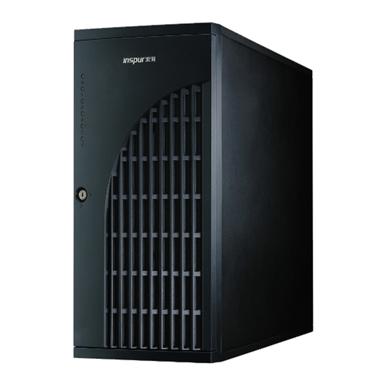
2.3 Product Appearance The effect picture of product appearance Product appearance 2.3.1 Front Panel The front door of this server can be locked by cabinet lock, as shown below: Front door diagram 8... - Page 13 Product Specifications Open the front door, you will see the front panel. According to different HDD types, the configuration can be divided into 2.5-inch HDD configuration and 3.5-inch HDD configuration. The following figures are just for reference, please subject to your purchased machine configuration.
- Page 14 Name System fault indicator Fan fault indicator Network status indicator Power fault indicator Reset button Power button Chassis safety lock Optical drive USB interface USB interface 0-7 hard disks 8-15 hard disks HDD failure alarm indicator HDD status indicator light Built-in hard disk 0 Built-in hard disk 1 Built-in hard disk 2...
- Page 15 Product Specifications 2.3.3 Rear Panel Rear panel view Name Power switch Power input interface Serial interface BMC Reset Gigabit Ethernet ports IPMI management interface USB interface ID light and ID button VGA interface PCI and PCI-E expansion slot Power supply fan System fan 11...
-
Page 16: Mainboard Layout
2.3.4 Mainboard Layout Name DIMMs (corresponding to CPU0) CPU0 System fan interfaces SATA interfaces SSATA interfaces Front USB interface Built-in USB interfaces CLR_CMOS jumper TCM interface Front VGA interface PCIE slots (corresponding to CPU0) PCIE slots (corresponding to CPU1) CPU1 fan interface Rear VGA interface ID light and button IPMI interface/rear USB interface (2) -
Page 17: Bios Configuration
3.1 System BIOS Configuration Methods Power on the server, system starts to boot, when the following content appears below Inspur logo on the screen: “Press <DEL> to SETUP or <TAB> to POST or <F12> to PXE Boot.”, press [DEL] button;... -
Page 18: Bios Configuration
Control key instruction table Press Key Function <Esc> Exit or return from sub-menu to main menu. <←> or <→> Select a menu. <↑> or <↓> Move the cursor up or down. <Home> or <End> Move the cursor to the top or bottom of the screen <+>... -
Page 19: Advanced Menu
BIOS Configuration 3.2.2 Advanced Menu Advanced Menu Interface Instruction Table Interface Parameters Function Description Trusted Computing Trustable computing configuration ACPI Settings Advanced configuration and power interface settings AST2400 Super IO Configuration AST2400 I/O chip parameter configuration Serial Port Console Redirection Serial port console redirection settings PCI Subsystem Settings PCI subsystem settings... - Page 20 Trusted Computing Menu Interface Instruction Table Interface Parameters Function Description Security Device Support BIOS security device support settings Current Status Information Status information of the current security device 3.2.2.2 ACPI Settings Advanced Menu Interface Instruction Table Interface Parameters Function Description Enable ACPI Auto Configuration To enable ACPI automatic configuration Lock Legacy Resources...
- Page 21 BIOS Configuration AST2400 Super IO Configuration Menu Interface Instruction Table Interface Parameters Function Description Super IO Chip The current I/0 chip Serial Port 1 Configuration Serial port 1 configuration 3.2.2.4 Serial Port Console Redirection Serial Port Console Redirection Menu Interface Instruction Table Interface Parameters Function Description Console Redirection...
- Page 22 Console Redirection Settings Menu Interface Introduction Interface Parameters Function Description Terminal Type Terminal type settings Bits per second Baud rate settings Data Bits Data bits settings Parity Parity check settings Stop Bits Stop bits settings Flow Control Flow control settings VT-UTF8 Combo Key Support VT-UTF8 Combo key support settings Recorder Mode...
- Page 23 BIOS Configuration 3.2.2.6 CSM Configuration CSM Configuration Menu Interface Instruction Table Interface Parameters Function Description CSM Support CSM support settings GateA20 Active A20 address line’s control mode settings Option Rom Message Option Rom display mode settings Boot option filter Boot option filter settings Option ROM execution Option Rom execution method Network...
- Page 24 USB Menu Interface Instruction Table Interface Parameters Function Description Legacy USB Support Legacy USB device settings Extensible host controller interface settings, orienting XHCI Hand-off to USB 3.0. Enhanced host controller interface settings, orienting to EHCI Hand-off USB2.0. USB Mass Storage Driver Support USB mass storage driver support settings Port 60/64 Emulation USB port 60/64h emulation settings...
- Page 25 BIOS Configuration 3.2.3 Chipset Menu Chipset Menu Interface Instruction Table Interface Parameters Function Description Processor Configuration Processor configuration Advanced Power Management Configuration Advanced power management configuration QPI Configuration QPI configuration Memory Configuration Memory configuration IIO Configuration IIO configuration PCH Configuration PCH configuration Server ME Configuration Server ME configuration...
- Page 26 Processor Configuration Menu Interface Instruction Table Interface Parameters Function Description Processor information submenu, and processor detailed Processor Information information. Hyper Threading Technology Hyper threading technology settings Core Enabled CPU core number settings Execute Disable Bit Execute disable bit settings Intel TXT Support Intel trusted execution technology support settings Intel virtual machine extensions technology settings Safe mode extension settings...
- Page 27 BIOS Configuration Advanced Power Management Configuration Menu Interface Instruction Table Interface Parameters Function Description Power Technology To set power management Config TDP TDP settings CPU P State control sub-menu, enabled when Power CPU P State Control Technology is set to [Custom]. CPU C State control sub-menu, enabled when Power CPU C State Control Technology is set to [Custom].
- Page 28 CPU C State Control CPU C State Control Menu Interface Instruction Table Interface Parameters Function Description Package C State limit C state limit settings CPU C3 report C3 enable/disable settings CPU C6 report C6 enable/disable settings Enhanced Halt State (C1E) C1E enable/disable settings Energy Performance Tunning 24...
- Page 29 BIOS Configuration Energy Performance Tunning Menu Interface Instruction Table Interface Parameters Function Description Energy Performance Tunning To select BIOS or OS to carry out energy performance tuning Energy PerformanceBIAS Energy performance management settings Workload Configuration Workload configuration 3.2.3.3 QPI Configuration QPI Configuration Menu Interface Instruction Table Interface Parameters Function Description...
- Page 30 3.2.3.4 Memory Configuration Memory Configuration Menu Interface Instruction Table Interface Parameters Function Description Enforce POR To execute POR settings Memory Frequency Memory frequency settings ECC Support ECC support settings Rank Multiplication Rank multiplication settings LRDIMM Module Delay LRDIMM module delay settings Data Scrambling Data scrambling settings Refresh Options...
- Page 31 BIOS Configuration Memory RAS Configuration Memory RAS Configuration Menu Interface Instruction Table Interface Parameters Function Description As for memory mode configuration, there’re 3 options of Memory Mode [Independent], [Mirroring] and [Lock Step]. Lockstep X4 DIMMs X4 DIMMs’ Lockstep enable/disable settings Memory Rank Sparing Memory Rank sparing settings Correctable Error Threshold...
- Page 32 IIO Configuration Menu Interface Instruction Table Interface Parameters Function Description IIO0 configuration sub-menu, used to set link speed of PCIE IIO0 Configuration device of CPU0. IIO1 configuration sub-menu, used to set link speed of PCIE IIO1 Configuration device of CPU1. I/OAT Configuration Intel I/O acceleration technology configuration sub-menu Intel VT for Directed I/O (VT-d)
- Page 33 BIOS Configuration PCH SATA Configuration Menu Interface Instruction Table Interface Parameters Function Description SATA Controller SATA controller switching settings As for SATA mode configuration, there’re two modes of [AHCI] and Configure SATA as [RAID] for setting. Information of hard disks connected to onboard SATA port SATA Port 0/1/2/3/4/5 0/1/2/3/4/5.
- Page 34 Press Key Description ↑↓ Used to move cursor in different menus or to change values of menu options. To select the next menu setting option. Enter To select a menu. To exit menu or return to previous menu from sub-menu. SATA RAID configuration interface has the following 4 executable menus: Create RAID Volume To create an RAID volume.
- Page 35 BIOS Configuration System displays the following menu options: Please enter a volume label name less than 16 characters without containing any Name special character. Please select RAID volume level, if no volume has been created at present, there’re four volume levels of RAID0 (Stripe), RAID1 (Mirror), RAID10 (RAID0+1) and RAID5 (Parity) for selection, please select volume level according to actual requirements.
- Page 36 After entering Delete RAID Volume menu, system prompts: “Deleting a volume will reset the disks to non-RAID. Warning : ALL DISKS DATA WILL BE DELETED.”. To delete an RAID volume, please press [DEL], system prompts: “ALL DATA IN THE VOLUME WILL BE LOST!” again. Are you sure you want to delete “Volume*”?(Y/N):”, to delete this RAID volume, please enter “Y”, to cancel deletion of this RAID volume, please enter “N”.
- Page 37 BIOS Configuration System prompts: “Are you sure you want to exit?(Y/N):”, enter “Y”, to exit SAS RAID configuration interface, enter “N”, to cancel exit operation. 3.2.3.7 Server ME Configuration Server ME Configuration Menu Interface Instruction Table Interface Parameters Function Description Operational Firmware Version Operational ME firmware version Recovery Firmware Version...
- Page 38 Common Configuration Menu Interface Instruction Table Interface Parameters Function Description MMCFG Base MMCFG base address settings Isoc Mode Isoc mode settings MeSeg Mode MeSeg mode settings Numa Numa switching settings BIOS Guard BIOS guarding settings VGA Priority Integrated video card and external video card priority settings. 3.2.4 Server Mgmt Server Mgmt Menu Interface Instruction Table Interface Parameters...
- Page 39 BIOS Configuration 3.2.4.1 System Event Log System Event log Menu Interface Instruction Table Interface Parameters Function Description SEL Components System event log enable/disable settings during startup Erase SEL System event log erase settings When SEL is Full Operation settings when SEL is full Log EFI Status Codes Log EFI status codes settings 3.2.4.2 View FRU Information...
- Page 40 3.2.4.3 BMC Network Configuration BMC network configuration Menu Interface Instruction Table Interface Parameters Function Description Configuration BMC Network Status Parameter: It could set Configuration Address Source static IPs, and obtain IPs dynamically, while [Unspecified] will not modify BMC network parameters. Current Configuration Address Current configuration address status Station IP adderess...
- Page 41 BIOS Configuration BIOS could carry out Dynamic and Static network settings on BMC Dedicated management port and sharelink management port, taking Dedicated management port as an example, to set a BMC Static IP as follows: Set the Configuration Address Source option to [Static] Select the Station IP Address option, and press Enter, to pop up the Station IP Address window, enter the Static IP to set manually, after configuration is completed, press Enter to confirm, and an example is as shown in the following...
- Page 42 3.2.4.4 BMC User Settings BMC User Settings Menu Interface Instruction Table Interface Parameters Function Description Add User The sub-menu for adding users Delete User The sub-menu for deleting users Change User Settings The sub-menu for changing user settings Add User operation 38...
- Page 43 BIOS Configuration Select the User Name option, and press Enter to pop up the User Name box, enter the user name to set manually, after configuration is completed, press Enter to confirm. Select the User Password option, and press Enter to pop up the User Password box, enter the user password to set manually, after configuration is completed, press Enter to confirm.
- Page 44 Select the User Name option, and press Enter to pop up the User Name box, manually enter the user name to delete, after configuration is completed, press Enter to confirm. Select the User Password option, and press Enter to pop up the User Password box, manually enter the user password to delete, after that, press Enter to confirm, and the BMC USER SETTINGS INFO prompt will pop up, indicating user password deletion is done or not.
- Page 45 BIOS Configuration 3.2.4.5 System Health Information System Health Information Menu Interface Instruction Table Interface Parameters Function Description System Temperature Information System temperature information sub-menu System Fan Speed System fan speed sub-menu System Voltage Information System voltage information sub-menu System Temperature Information 41...
- Page 46 System Fan Speed System Voltage Information 42...
-
Page 47: Security Menu
BIOS Configuration 3.2.5 Security Menu Security Menu Interface Instruction Table Interface Parameters Function Description Administrator Password Create a password for administrator User Password Create a password for normal user 3.2.6 Boot Menu 43... - Page 48 Boot configuration Menu Interface Instruction Table Interface Parameters Function Description Bootup NumLock State Numlock state settings after bootup Boot Options Retry The booting device polling settings To boot quietly, set this option to Enabled, and boot logo Quiet Boot displays as that set by manufacturer, disabled, boot logo displays as AMI’s default logo.
-
Page 49: Firmware Update
BIOS Configuration 3.2.7 Save & Exit Menu Save & Exit Menu Menu Interface Instruction Table Interface Parameters Function Description Save Changes and Exit To save changes and exit Discard Changes and Exit To discard changes and exit Save Changes and Reset To save changes and reset Discard Changes and Reset To discard changes and reset... - Page 50 When there’s no change in ME part, to update BIOS part, it is only required to execute command: afudos BIOS.bin /b /p /n /x. Parameter instructions: /b -- Program Boot Block /p -- Program Main BIOS /n -- Program NVRAM /x -- Don’t Check ROM ID /me -- Program ME Entire Firmware Block Use afudos tool to update BIOS in Linux OS...
- Page 51 BIOS Configuration There’re 32bit and 64bit Windows OS afuwin tools, and afuwinx64.exe is used in 64bit OS, run a command prompt, to enter the directory containing afuwinx64.exe tool, meanwhile, put bin files of corresponding BIOS into this folder, and enter command: afuwinx64.exe BIOS. BIN /P /B /N /X /R, to update BIOS files.
- Page 52 Select Program all Blocks and Do Not Check ROM ID options on Setup interface, click flash button, system enters Progress interface automatically, and executes BIOS update according to colors shown on the right, thus BIOS update is done as shown in the following figure: 48...
-
Page 53: Bmc Settings
This chapter introduces specifications abided by the management software and main functions. Inspur server management software is a control unit for server management, which is compatible with management standard IPMI2.0 specification in server industry. It mainly realizes the following functions: ●... -
Page 54: Functional Modules
4.2 Functional Modules This chapter introduces Inspur server management system module composition as well as functions of these modules. 4.2.1 Module Composition Inspur server management system is mainly composed of IPMI module, command line module, WEB module, KVM Over IP and virtual media. -
Page 55: Web Interface Introduction
BMC Settings Note: If the Java runtime environment does not meet the requirement, please download from: http://www.oracle.com/technetwork/java/javase/downloads/index.html 4.3 Web Interface Introduction About this chapter It introduces Web interface of management system as well as operation steps to login Web interface. ●... - Page 56 4.3.2 Web Interface Introduction The Web interface helps users to accomplish server management via its visual and friendly interface, and the Web interface contains online help, so users could query instructions and operation guide on this interface via clicking button on any interface.
- Page 57 BMC Settings following figure. 4.3.4 System Information Select “System Information” on navigation tree, which includes six interfaces of asset information, hardware monitor, system device status, BIOS setup options, FRU information and history, as shown in the following figure. ● Asset information: Display system configuration information, which includes CPU, memory, PCIE device, onboard NIC and power supply unit information.
- Page 58 54...
-
Page 59: Storage
BMC Settings 4.4 Storage Select “Storage” on navigation tree to open the storage interface, which contains four interfaces of controller, physical drives, logical drives and enclosure, as shown in the following figure. ● Controller: Display the controller information of the storage system. ●... -
Page 60: Remote Control
4.5 Remote Control Select “Remote Control” on navigation tree, to open the remote control interface, which contains six interfaces of console redirection (KVM)”, server power control, server location, configure remote session, virtual media devices and mouse modes settings, as shown in the following figure. - Page 61 BMC Settings media connection methods. ● Virtual media devices: To set the quantity of virtual media (floppy disks, CD drives and hard disks etc.) ● Mouse modes settings: To set the mouse working mode for KVM remote console. 57...
-
Page 62: Power Supply And Fan
4.6 Power Supply and Fan Select “Power Supply and Fan” on navigation tree, to open the power supply and fan page, which contains one page of fan speed control, as shown in the following figure. ● Fan speed control: Contain fan status, current speed information and speed control function. - Page 63 BMC Settings and network interface bonding function. ● Services: Configure BMC’S Web service, KVM service, ssh service, telnet service, etc. ● NTP settings: Set BMC time, which has two methods: Synchronize from NTP server. Set time manually. ● SMTP settings: Set the SMTP server information related to alert.
- Page 64 60...
- Page 65 BMC Settings 61...
-
Page 66: Logs
4.8 Logs Select “Logs” on navigation tree, to open related log page, which contains five pages of system event log, BMC system audit log, black box log, event log setting and system and audit log settings, as shown in the following figure. ●... - Page 67 BMC Settings 63...
-
Page 68: Fault Diagnosis
4.9 Fault Diagnosis Select “Fault Diagnosis” on navigation tree, to open fault diagnosis page, which contains three pages of BMC recovery, capture screen and host POST code, as shown in the following figure. ● BMC recovery: Contain two functions of BMC warm reset and KVM service restart; ●... - Page 69 BMC Settings ● BIOS firmware update: Update BIOS FW via BMC Web interface; ● Restore factory defaults: Restore BMC’s configuration to factory state. ● System administrator: Set administrator’s information. 65...
-
Page 70: Command Line Function Introduction
4.11 Command Line Function Introduction About this chapter It introduces Web interface of management system as well as operation steps to login Web interface. ● Login command line Introduce methods of login command line. ● Command line function introduction Introduce command line functions. 4.11.1 Command Line Login Login to BMC Command line through ssh, default user name: root, and default password: rootuser. - Page 71 BMC Settings Enter help, you could view online help: 4.11.2 Command Line Function Introduction 4.11.2.1 Network Information Acquisition and Configuration: You could acquire and configure BMC’s network information via ipconfig instruction: 4.11.2.2 Sensor Information Acquisition: Via sensor instruction, you could acquire the information list of all sensors: 67...
- Page 72 4.11.2.3 FRU Information Acquisition and Configuration: Via FRU instruction, you could acquire FRU configuration information: 4.11.2.4 Chassis Status Acquisition and Control: Via chassis instruction, you could acquire and control system power status. Acquire system power status: 4.11.2.5 User Acquisition, Adding and Deleting: Via user instruction, you could acquire the user list, add or delete users.
- Page 73 BMC Settings Acquire user list: 4.11.2.6 BMC Version Acquisition and BMC Restart Via mc instruction, you could acquire BMC version information, and restart BMC. Acquire BMC version information: 4.11.2.7 Fan Work Mode Configuration and Fan Speed Acquisition: Via fan instruction, you could set fan work mode, and acquire fan speed. 69...
- Page 74 Fan speed acquisition: 4.11.2.8 Power Module Information Acquisition and Configuration: Via Psu instruction, you could acquire power module information, and set power module as main output. Power module information acquisition: 4.11.2.9 Change Root Password: Via password instruction, you could change root user’s password: 70...
-
Page 75: Time Zone Table
BMC Settings 4.12 Time Zone Table Time Zone Countries and Regions GMT-12:00 West Date Line GMT-11:00 Appiah, Niue, Pago Pago, Midway GMT-10:00 Fakaofo, Rarotonga, the island of Tahiti, Johnston, Hawaii GMT-09:30 Marquesas GMT-09:00 Alaska, Gambier Islands GMT-08:00 Pacific Time (USA and Canada), Pitcairn, Whitehorse, Tijuana, Vancouver Mountain Time (USA and Canada), Edmonton, Hermosillo, the Tao gave birth GMT-07:00 to Crick, Chihuahua, Yellowknife, Arizona, Mazatlan... - Page 76 Antananarivo, Baghdad, Bahrain, Dar Es Salaam, Djibouti, Qatar, ha Khartoum, GMT+03:00 Kampala, Comoros, Kuwait, Mayotte, Riyadh, Mogadishu, Moscow, Nairobi, Addisababa, Aden, Showa GMT+03:30 Newfoundland Baku, Dubai, Tbilisi, Reunion Island, Mahe, Muscat, Mauritius, Samarra, Ye GMT+04:00 Liewan GMT+04:30 Kabul Aktau Aktobe, Ashkhabad, Karachi, Dushanbe, Kell islands, Maldives, Kelang, GMT+05:00 Yekaterinburg, Tashkent GMT+05:30...
-
Page 77: Common Faults, Diagnosis And Troubleshooting
Common Faults, Diagnosis and Troubleshooting 5 Common Faults, Diagnosis and Troubleshooting This chapter introduces the common server faults as well as corresponding diagnosis and troubleshooting suggestions. 5.1 Common Faults No power after startup After the machine is connected with power cable, no power is provided for the machine while pressing the On/Off button;... - Page 78 If there’s a machine and a power module of the same type, you could change the power module to test whether there’s a power module fault; If above operations could not solve the problem, please contact Inspur customer service. Power module indicator off or red indicator on Description: The machine is under normal operation, but a certain power module indicator is off or the red light is on.
- Page 79 Operation steps: Please check whether all power module indicators are steadily green, if so, you can login BMC web interface to collect logs, and contact Inspur customer service. Memory capacity incomplete Description: Memory capacity viewed via the operating system does not correspond with physical memory capacity.
- Page 80 If the USB device is normal when connecting to other hosts, the server may be abnormal, please call Inspur technical hotline for support; if the USB device turns out to be abnormal when connecting to other hosts, please replace the USB device.
-
Page 81: Services
6.1.1.2 Necessary Debugging Preparations When turning to Inspur for technical support, Inspur technical support engineers may help you carry out some operations, to further collect fault information or make troubleshooting directly, so please collect necessary fault information before turning to technical support, and prepare tools such as screwdriver, screws, serial cable and Ethernet cable, etc. - Page 82 Contact Information Name Mobile/Phone (Ext.) Machine Serial No. 21xxxxxxx or 8000xxxxx Problem or Fault Description Description content Attachments Fault pictures or log files. 6.2.4 Website Service Inspur official website: www.inspur.com Technical support website: www.4008600011.com 6.2.5 Hotline Service Hotline: 4008600011 78...
-
Page 83: Certifications & Standards
Certifications & Standards 7 Certifications & Standards This chapter introduces the certifications achieved by this product and standards it complies with. ● China CCC Introduce CCC standards abided by the product 7.1 China CCC This chapter introduces the CCC standards abided by this product. This product is a Class A product. - Page 84 Table of Hazardous Substances or Elements’ Name & Content – Server Hazardous Substances or Elements Part Name Cr(VI) PBDE Chassis × ○ ○ ○ ○ ○ Mainboard × ○ ○ ○ ○ ○ Memory ○ ○ ○ ○ ○ ○ Hard Drive ○...
Need help?
Do you have a question about the NP5570M4 and is the answer not in the manual?
Questions and answers