Table of Contents
Advertisement
Quick Links
Advertisement
Table of Contents

Related Manuals for Inspur NX5460M5


Summary of Contents for Inspur NX5460M5
- Page 1 Inspur Server User Manual NX5460M5...
- Page 2 Inspur. The information in this manual is subject to change without notice. Inspur is the registered trademark of Inspur. All the other trademarks or registered trademarks mentioned in this manual are the property of their respective holders.
- Page 3 4.Please install the product-compatible operating system and use the driver provided by Inspur. If you use an incompatible operating system or non-Inspur driver, it may cause compatibility issues and affect the normal use of the product, Inspur will not assume any responsibility or liability.
-
Page 4: Table Of Contents
Contents 1 Safety Instructions ......................... 1 2 Product Specification ........................5 2.1 Introduction ..........................5 2.2 Feature ............................6 3 Component Identification ......................7 3.1 Front Panel Components ......................7 3.2 CLR_CMOS Jumper Introduction ....................7 4 Operations ............................. 9 4.1 Power up the Server ........................ - Page 5 8 BMC Settings ..........................65 8.1 Introduction ..........................65 8.2 Functional Modules ........................66 8.3 Web Interface Introduction ......................67 8.4 Storage ............................72 8.5 Remote Control .......................... 72 8.6 Power and Fan ..........................74 8.7 BMC Settings ..........................78 8.8 Logs ............................
- Page 6 12 Electrostatic Discharge ........................ 111 12.1 Preventing Electrostatic Discharge ................... 111 12.2 Grounding Methods to Prevent Electrostatic Discharge ............111 13 Warranty ............................112 13.1 Introduction ..........................112 13.2 Warranty Service ........................112 13.3 Warranty Exclusions ......................... 113...
-
Page 7: Safety Instructions
For your safety, please do not attempt to remove the cover of the system to remove or replace any component without assistance provided by Inspur. Only service technicians trained by Inspur are authorized to remove the cover of the host, and to remove and replace internal components. - Page 8 In the event of the following, please unplug the power line plug from the power socket and contact Inspur’s customer service department: The power cables, extension cables or power plugs are damaged.
- Page 9 Close the host cover, reconnect the system to the power socket, and then power on. In case of operation failure or other abnormal situations, please contact Inspur and get technical support.
- Page 10 Upon receiving the proper authorization from Inspur and dismounting the internal components, please pay attention to the following: Switch the system power supply off and disconnect the cables, including all connections of the system.
-
Page 11: Product Specification
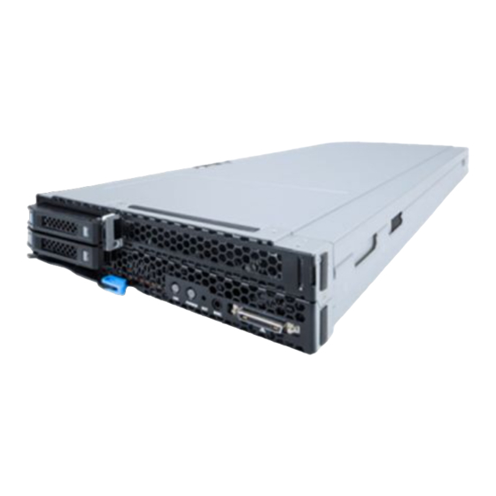
2 Product Specification 2.1 Introduction Inspur NX5460M5 is a half-width 2S blade server, which is designed on the basis of the new generation of Intel® Xeon® scalable processor. The product is optimized for cloud computing, virtualization, HPC and other requirements: Ultra-high performance: Supports a full range of CPUs (up to 205W) with a new ●... -
Page 12: Feature
2.2 Features and Specifications Processor Processor Type Intel® Skylake series processors Chipset Chipset Type Intel® C62x Chipset Family Memory Memory Type ECC Registered DDR4, RDIMM, LRDIMM, NVDIMM Memory Slot Qty. Total Memory Capacity Supports up to 3TB (128GB per memory) Front: 2 USB2.0 ports + 1 USB3.0 port Internal: 1 USB3.0 port Front: 1 VGA port... -
Page 13: Component Identification
Component Identification 3 Component Identification 3.1 Front Panel Components Front View Item Name & Function HDD 1/0 Handle UID button/LED Used to locate the compute node to be operated in the rack; turn on/off the light through manual pressing/ BMC remote control. Off: The compute node is not located. - Page 14 Item Description Function CLR_CMOS Short-circuit Pin1/2, restore to normal status; short-circuit CMOS clear jumper (J54) Pin2/3, clear CMOS. Note: It is required to shut down the system, as well as disconnect the power supply during CMOS clearing. Hold for 5 seconds after short-circuiting Pin2/3, and then short-circuit Pin1 and Pin2 (the default status) of CLR_CMOS jumper with a jumper cap, to restore to its original status.
-
Page 15: Operations
Operations 4 Operations 4.1 Power up the Server Insert the power cord plug, then press the Power Button. 4.2 Power down the Server WARNING: To reduce the risk of personal injury, electric shock, or damage to the equipment, remove the power cord to remove power from the server. The front panel Power Button does not completely shut off system power. -
Page 16: Remove The Access Panel
4.4 Remove the Access Panel WARNING: To reduce the risk of personal injury from hot surfaces, allow the drives and the internal system components to cool before touching them. CAUTION: For proper cooling, do not operate the server without the access panel, air baffle, or fan installed. -
Page 17: Setup
Setup 5 Setup 5.1 Optimum Environment When installing the server in a rack, select a location that meets the environmental standards described in this section. 5.1.1 Temperature Requirements To ensure continued safe and reliable equipment operation, install or position the system in a well-ventilated, climate-controlled environment. - Page 18 Because of the high ground-leakage currents associated with multiple servers connected to the same power source, Inspur recommends the use of a PDU that is either permanently wired to the building’s branch circuit or includes a nondetachable cord that is wired to an industrial-style plug.
-
Page 19: Identifying The Contents Of The Server Shipping Carton
5.4 Installing the Operating System To operate properly, the server must have a supported operating system installed. For the latest information on supported operating systems, refer to the Inspur website (http://www. inspur.com). Installing an operating system on the server may require you to obtain additional drivers... -
Page 20: Hardware Options Installation
6 Hardware Options Installation Introduction If more than one option is being installed, read the installation instructions for all the hardware options and identify similar steps to streamline the installation process. WARNING: To reduce the risk of personal injury from hot surfaces, allow the drives and the internal system components to cool before touching them. - Page 21 Hardware Options Installation Remove the heatsink. Install the processor: Step 1: Align the Clip’s triangle mark with the CPU’s corner mark, and then assemble the Clip and CPU together. Step 2: Align the heatsink position marked by “1” with the Clip’s triangle mark, vertically align the mounting holes on the heatsink with those on the Clip, and assemble the heatsink and Clip together.
- Page 22 Step 3: Install the assembled heatsink module onto the CPU socket, and the position marked by “1” should be aligned with the triangle mark on the CPU socket. Tighten the screws according to the sequence of 1, 2, 3, 4.
-
Page 23: Memory Option
Hardware Options Installation Notes: ● It is required to coat thermal grease evenly onto the contact position between CPU heatsink and CPU. ● During fixing CPU heatsink, it is required to fasten screws according to the sequence accordingly. 6.2 Memory Option ●... -
Page 24: Hot-Plug Hdd Option
automatically secure the DIMM, locking it into place. 6.3 Hot-plug HDD Option CAUTION: For proper cooling, do not operate the server without the access panel, baffles, expansion slot covers, or blanks installed. If the server supports hot-plug components, minimize the amount of time the access panel is open. Determine the status of the hard disk drive from the hot-plug HDD LED. - Page 25 Hardware Options Installation Step 2: Remove the HDD tray out of the chassis. Step 3: Remove the four screws on the two sides of the tray, and remove the old hard drive. Step 4: Install a new hard drive into the tray, and install it back into the server. Close the lever to fix the tray firmly.
-
Page 26: Bios Setup
Power on the server. The system will then start to boot. When the following content appears below Inspur logo on the screen: “Press <ESC> to Front Page or <DEL> to Setup or <F11> to Boot Menu or <F12> to PXE Boot.” Press DEL key. When “Entering Setup …” appears in the lower right corner of the screen, it will enter the BIOS setup soon. - Page 27 BIOS Setup Other hotkeys function: ESC: Enter BIOS Front Page interface. • • DEL: Enter BIOS Setup interface. • F11: Enter the BIOS Boot Manager interface, select the boot device. F12: Boot the PXE. • BIOS Setup Interface Control Key Instruction Table Function <Esc>...
-
Page 28: Bios Parameter Description
7.2 BIOS Parameter Description 7.2.1 Front Page When Inspur Logo appears during system boot, press ESC to enter the BIOS Front Page interface, as shown in the following figure: Front Page Interface Instruction Table Interface Parameters Function Description Product Name... - Page 29 BIOS Setup Setup Utility option on the Front Page interface to enter the BIOS Setup Main interface. BIOS Main interface contains the basic information of BIOS system, the version information of BIOS, BMC and ME, CPU model information, total memory capacity information and system time.
- Page 30 7.2.3 Advanced Menu Advanced interface includes the BIOS system parameters and related function settings, as shown in the follow figure and table. Advanced Interface Instruction Table Interface Parameters Function Description Peripheral Configuration Peripheral devices configuration options menu SIO AST2500 SIO configuration options menu Socket Configuration Socket configuration options menu ME Configuration...
- Page 31 BIOS Setup 7.2.3.1 Peripheral Configuration Peripheral Configuration interface is used for system peripheral device settings, as shown in the follow figure and table. Peripheral Configuration Interface Instruction Table Interface Parameters Function Description Default Value PCIe SR-IOV PCIe device SR-IOV setting Enabled PCIe ARI ARI capability setting...
- Page 32 SIO AST2500 Interface Instruction Table Interface Parameters Function Description Default Value Enable Serial Port A Enable/disable serial port A 7.2.3.3 Socket Configuration Socket Configuration interface is used for system processor and memory related settings, as shown in the following figure and table.
- Page 33 BIOS Setup Socket Configuration Interface Instruction Table Interface Parameters Function Description Processor Configuration Processor configuration submenu Common RefCode Configuration RC configuration submenu UPI Configuration UPI configuration submenu Memory Configuration Memory configuration submenu IIO Configuration IIO configuration submenu Advanced Power Management Configuration Advanced power management configuration submenu 7.2.3.3.1 Processor Configuration Processor Configuration interface is used for system processor related settings, as shown in...
- Page 34 Processor Configuration Interface Instruction Table Interface Parameters Function Description Default Value Per-Socket Configuration Per-Socket setting submenu Per-Socket Information Per-Socket information display submenu Hype-Threading [ALL] Logical processor thread setting Enabled Execute Disable Bit Virus protecting technology setting Enabled Enable Intel(R) TXT Intel trustable execution technology setting Disabled Intel hardware-assisted virtualization technology settings...
- Page 35 BIOS Setup Per-Socket Configuration Interface Instruction Table Interface Parameters Function Description Default Value Display the current available core Bitmap in hex Available Core Bitmap (Hex) Disable CPU core settings Core Disable Bitmap (Hex) Display enabled CPU cores Enable Core Bitmap (Hex) Display enabled core count Desired Core Count...
- Page 36 Per-Socket Information menu displays the current CPU information, as shown below : 7.2.3.3.2 Common RefCode Configuration Common RefCode Configuration interface is used for common settings, as shown in the following figure and table.
- Page 37 BIOS Setup Common RefCode Configuration Interface Introduction Interface Parameters Function Description Default Value Chose socket to output serial message MRC serial message display setting Socket0 MMIO High Granularity Size MMIO high resources granularity size setting 256G Numa Numa switching setting Enabled 7.2.3.3.3 UPI Configuration UPI Configuration interface is used for UPI related settings, as shown in the following figure...
- Page 38 UPI General Configuration Interface Instruction Table Interface Parameters Function Description Default Value UPI Status UPI status display submenu Link Frequency Select UPI link frequency setting Auto Link L0p Enable UPI link power saving mode settings Auto Link L1 Enable In the case that system is extremely idle, turn off QPI Link. Auto SNC setting Disabled Bus resources allocation ration can be configured by entering UPI Per Socket...
- Page 39 BIOS Setup UPI Per Socket Configuration Interface Instruction Table Interface Parameters Function Description Default Value Bus Resources Allocation Ratio PCIe Bus resources allocation ratio of each CPU 7.2.3.3.4 Memory Configuration Memory Configuration interface is used for memory related settings, as shown in the following figure and table.
- Page 40 Memory Configuration Interface Instruction Table Interface Parameters Function Description Default Value Enforce POR Enforce POR settings Auto Memory Frequency Memory frequency selection Auto Data Scrambling for DDR4 Data scrambling setting Auto Memory Topology Memory topology submenu Memory RAS Configuration Memory RAS setting submenu BSSA Configuration Menu BSSA configuration menu Select Memory Topology menu, and it will display the memory topology information, as...
- Page 41 BIOS Setup Select Memory RAS Configuration menu, and it will display the memory RAS configuration options, as shown below:...
- Page 42 Memory RAS Configuration Interface Instruction Table Interface Parameters Function Description Default Value Operation RAS mode Display current operation RAS mode Operation ext RAS mode Display current operation extra RAS mode Support RAS mode Display supported RAS mode Support ext RAS mode Display supported extra RAS mode Mirror Mode Mirror mode setting...
- Page 43 BIOS Setup 7.2.3.3.5 IIO Configuration IIO Configuration interface is used for PCIe slot settings, as shown in the following figure and table. IIO Configuration Interface Instruction Table Interface Parameters Function Description Default Value Socket# Configuration Socket# IIO Configuration setting submenu Intel VT for Directed I/O (VT-d) Intel VT-d switching setting submenu Intel VMD setting, to enable/disable the VMD of...
- Page 44 Advanced Power Management Configuration Interface Instruction Table Interface Parameters Function Description CPU P State Control CPU P state control configuration submenu CPU C State Control CPU C state control configuration submenu Package C State Control Package C state setting submenu CPU-Advanced PM Tuning CPU advanced PM turning setting submenu Select CPU P State Control menu to set the related options of CPU P state, as shown below:...
- Page 45 BIOS Setup CPU P State Control Interface Instruction Table Default Value Interface Parameters Function Description Enabled Uncore Fre Scaling (UFS) Uncore frequency limit setting Enabled SpeedStep (Pstates) SpeedStep on/off setting Enabled Turbo Mode Turbo mode setting Select CPU C State Control menu to set the related options of CPU C state, as shown below: CPU C State Control Interface Instruction Table Default Value...
- Page 46 Package C State Control Interface Instruction Table Default Value Interface Parameters Function Description Package C State Package C state setting C0/C1 State Select CPU-Advanced PM Tuning menu, select Energy Perf BIAS, and enter power performance setting interface, as shown below:...
- Page 47 BIOS Setup Energy Perf BIAS Interface Instruction Table Interface Parameters Function Description Default Value Power Performance Tuning Power performance tuning setting OS Controls EPB ENERGY_PERF_BIAS_CFG mode Performance setting Balanced Performance 7.2.3.4 ME Configuration ME Configuration interface displays the information related with ME configuration. The general information of ME configuration will be displayed by entering Server ME Configuration submenu, as shown below:...
- Page 48 Sever ME Configuration Interface Instruction Table Interface Parameters Function Description ME-BIOS Interface Ver. ME BIOS interface version ME SKU ME SKU ME Firmware Type ME FW type Operational Firmware Version Current operational ME FW version Backup Firmware Version Backup ME FW version Recovery Firmware Version Recovery ME FW version...
- Page 49 BIOS Setup PCH Configuration Interface Instruction Table Interface Parameters Function Description PCH Devices Intel IO control hub device setting submenu PCH Express Configuration PCH Express devices display and setting submenu PCH SATA Configuration PCH SATA configuration submenu PCH sSATA Configuration PCH sSATA configuration submenu USB Configuration PCH USB configuration submenu...
- Page 50 PCH Devices Interface Instruction Table Default Value Interface Parameters Function Description PCH state after G3 Select S0/S5 for ACPI state after a G3 7.2.3.5.2 PCI Express Configuration PCH Express Configuration interface is used to set the options related with PCH PCIe, as shown in the following figure and table.
- Page 51 BIOS Setup PCI Express Configuration Menu Interface Instruction Table Interface Parameters Function Description Default value PCI-E ASPM Support (Global) Setting ASPM support for all downstream devices L1 Only PCIE Ports X Bifurcation Bifurcation of PCIe port X 7.2.3.5.3 PCH SATA Configuration/PCH sSATA Configuration PCH SATA Configuration/PCH sSATA Configuration interface is used to set the onboard PCH SATA/sSATA options, as shown in the following figures.
- Page 52 PCH SATA Configuration Menu Interface Instruction Table Interface Parameters Function Description Default value SATA Controller Enable or disable SATA controller Enabled Configure SATA as Set the SATA Controller as AHCI or RAID AHCI Port X Control Enable or disable SATA port X Enabled Port X Status SATA port X status...
- Page 53 BIOS Setup Take SATA RAID configuration in Legacy Mode as an example to introduce the SATA RAID configuration. During system startup, the screen will prompt: Press <CTRL-I> to enter Configuration Utility... Press <Ctrl> and <I> simultaneously to enter the SATA RAID configuration, as shown in the following figure.
- Page 54 Key Instruction Table Description ↑↓ Used to move cursor in different menus or to change values of menu options. To select the next menu option. Enter To select a menu. To exit menu or return to previous menu from submenu. Menu Instruction Table Create RAID Volume To create an RAID volume.
- Page 55 BIOS Setup Create RAID Menu Instruction Table Interface Parameters Function Description Please enter a volume label name less than 16 characters without containing any Name special characters. Please select RAID volume level. If no volume has been created at present, there are four volume levels of RAID0 (Stripe), RAID1 (Mirror), RAID10 (RAID0+1) and RAID5 (Parity) for selection.
- Page 56 volume, please enter “Y”, to cancel the deletion, please enter “N”. Reset Disks to Non-RAID menu. After entering Reset Disks to Non-RAID menu, system will display all HDDs in RAID volume. Please use the space key to select the HDD to reset according to the actual demand, and then press Enter to reset the HDD.
- Page 57 BIOS Setup noted that all data on this disk will be lost as the spare disk. Exit menu. Use the up and down keys to move to the Exit menu or press the ESC key to exit the SATA RAID configuration interface, as shown below. The system prompts: “Are you sure you want to exit? (Y/N):”, enter “Y”...
- Page 58 After entering sSATA RAID configuration interface, it will display the Create RAID Volume option, the existed RAID volumes (if present) information and non-RAID physical disks information.
- Page 59 BIOS Setup Create RAID Volume. Enter this menu interface, as shown below. Create RAID Menu Instruction Table Interface Parameters Function Description Please enter a volume label name less than 16 characters without containing any Name special characters. Please select RAID volume level. If no volume has been created at present, there are four volume levels of RAID0 (Stripe), RAID1 (Mirror), RAID10 (RAID0+1) and RAID5 (Parity) for selection.
- Page 60 Delete RAID Volume. Select a created RAID volume, and press Enter to view the RAID volume information. If you want to delete the RAID volume, select Delete, and press Enter to confirm it.
- Page 61 BIOS Setup 7.2.3.5.4 USB Configuration USB Configuration interface is used to set USB related options, as shown in the following figure and table. USB Configuration Interface Instruction Table Interface Parameters Function Description Default value Enabled USB2.0 Port0 Connector High-density blue port USB2.0 setting Enabled USB2.0 Insyde Port Connector Chassis internal USB2.0 setting...
- Page 62 H2oUve Configuration Interface Instruction Table Interface Parameters Function Description Default Value H2OUVE Support Enable/disable H2OUVE support Enabled 7.2.3.5.6 IPMI Configuration IPMI Configuration interface is used to set IPMI related options, as shown in the following figure and table.
- Page 63 BIOS Setup IPMI Configuration Interface Instruction Table Interface Parameters Function Description Default Value IPMI Support IPMI support switch setting Enabled System Interface Type System interface type of connecting BMC display -- BMC Status Current BMC status display BMC Firmware Version BMC firmware version IPMI Specification Version IPMI specification version A maximum waiting time period from POST to...
- Page 64 BMC Configuration Menu Interface Instruction Table Interface Parameters Function Description Default Value Watchdog Timer Support Enable or disable BMC watchdog timer at start of POST Disabled Not disable in OS Enable or disable BMC watchdog timer when boot to OS Disabled Watchdog Timer Timeout Watchdog expiration time setting Watchdog Timer Action...
- Page 65 BIOS Setup Modify the IP address acquisition mode of this port to DHCP through IPV4 source. Select Exit -> Save Change Without Exit option to save, it takes effect immediately. BMC static IP setting method: Select Dedicated or Share BMC port. Modify the IP address acquisition mode of this port to Static through IPV4 source.
- Page 66 7.2.5 Power Power interface is used to set the options related with system power status, as shown in the following figure and table. Power Interface Instruction Table Interface Parameters Function Description Default Value Auto wake on S5 setting. When set to Enabled, Auto Wake on S5 you can set to wake up the machine from S5 state Disabled...
- Page 67 BIOS Setup Boot Interface Instruction Table Interface Parameters Function Description Default Value Boot Type Select boot type UEFI Boot Type Network Stack Network stack support setting Enabled PXE Boot capability PXE boot setting UEFI:IPv4 PXE Retry Support PXE retry support setting Enabled PXE Retry Count PXE retry count setting...
- Page 68 Legacy Boot Configuration Interface Instruction Table Interface Parameters Function Description Default Value Boot Type Select boot type Legacy Boot Type PXE Boot capability PXE boot setting Enabled Enabled PXE Retry Support PXE retry support setting PXE Retry Count PXE retry count setting Boot Type Order Boot type order setting Legacy boot option setting submenu, the boot...
-
Page 69: Firmware Update
7.3.1 Update BIOS in UEFI Shell When Inspur Logo appears during system startup, there is a prompt “Press <ESC> to Front Page or <DEL> to Setup or <F11> to Boot Menu or <F12> to PXE Boot.” on the bottom of the screen. - Page 70 bin -ALL -BIOS –SSB to flash BIOS only, as shown in the following figure. Note: After updating ME+BIOS, please power off the machine, confirm that there is no residual electricity on the motherboard, and then power it on. 7.3.2 Update BIOS in Linux There’re 32bit and 64bit Linux OS H2OFFT tools.
- Page 71 This section introduces the specifications that the management software follows and its main functions. The Inspur Server Management System is a control unit for server management, which is compatible with the management standard IPMI2.0 specification. Below are the main functions of the Inspur Server Management System: ●...
- Page 72 This chapter introduces the Inspur Server Management System module composition, as well as the functions of these modules. 8.2.1 Module Composition The Inspur Server Management System is mainly composed of IPMI module, command line module, WEB module, KVM Over IP and virtual media. ●...
- Page 73 BMC Settings devices via local video, keyboard and mouse to the client, enabling the operation of remote devices in real-time. ● Virtual Media: A method of providing remote access on local media (CD-ROM, floppy drive or CD/floppy disk iso file) in the form of virtual CD driver and floppy drive on server via the internet. To use the remote control function, the client should be equipped with appropriate browser and Java runtime environment.
- Page 74 Note: The system provides a default user “admin” in administer user group, and the default password is “admin”. Please change the default password in time after the first login. 2. Click “Login”, to enter the management interface. 8.3.2 Web Interface Introduction The Web interface helps users accomplish server management.
- Page 75 BMC Settings ● The name of the Web interface is displayed on top left of the interface. ● The meanings of all buttons on top right of the interface: Click on the Overview button, to return to the overview page. ...
- Page 76 ● Specific operation interface is on the right of the interface. 8.3.3 Overview Click on Overview to open the “General Information” interface, as shown below. 8.3.4 Information Select “Information” on the navigation tree. It contains the interfaces of system information, BIOS setup options, FRU information and history record, as shown in the following figures below.
- Page 77 BMC Settings...
- Page 78 8.4 Storage Select “Storage” on the navigation tree to open the storage interface. At present, the storage information control only supports LSI RAID card. This interface contains controller, physical drives, and logical drives information, as shown in the following figures. 8.5 Remote Control Select “Remote Control”...
- Page 79 BMC Settings...
- Page 80 8.6 Power and Fan Select “Power Supply and Fan” on the navigation tree to open the power supply and fan interface. It contains the interfaces of server power control, power peak and power consumption, as shown in the following figures. ●...
- Page 81 BMC Settings 8.7 BMC Settings Select “BMC Settings” on the navigation tree to open the BMC Settings interface. It contains the interfaces of BMC network, services, NTP, SMTP, alerts, access control and BIOS boot options, as shown in the following figures. ●...
- Page 83 BMC Settings...
- Page 84 8.8 Logs Select “Logs” on the navigation tree to open the related log interface. It contains the interfaces of system event log, BMC system audit log, black box log, event log setting, BMC system audit log setting and one-key collect log, as shown in the following figures. ●...
- Page 85 BMC Settings...
- Page 87 BMC Settings 8.9 Fault Diagnosis Select “Fault Diagnosis” on the navigation tree to open the fault diagnosis interface. It contains the interfaces of BMC self-inspection result, BMC recovery, capture screen and host POST code, as shown in the following figures. ●...
- Page 88 8.10 Administration Select “Administration” on the navigation tree to open the administration interface. It contains the interfaces of user administration, security, dual image configuration, dual firmware update, BIOS firmware update, CPLD update and restore factory defaults, as shown in the following figures. ●...
- Page 89 BMC Settings ● Dual image configuration: To configure the boot options in dual image mode via BMC Web interface. ● Dual firmware update: To update BMC FW via BMC Web interface. ● BIOS firmware update: To update BIOS FW via BMC Web interface. ●...
- Page 91 BMC Settings 8.11 Service & Protocol BMC support network connection manager library to configure networking services configuration in run-time. RCMP+, HTTP/HTTPS, KVM, CD-MEDIA, FD-MEDIA, HD-MEDIA, SSH, TELNET and SOLSSH services are supported so far. User can enable or disable theses services, configure communication port, the session timeout value of the service and the maximum number of allowed sessions for the services.
- Page 92 Non- Default Default Service Usage Security Security Port Timeout(s) State Port Session Port RMCP+ IPMI Enable 1800 Http/Https WEBGUI Enable 80(Http) 443(Https) 443(Https) 1800 Console Enable 7578 7582 7578 1800 Redirection cd-media Virtual Media Enable 5120 5124 5120 fd-media Virtual Media Enable 5122 5126 5122...
- Page 93 BMC Settings User 1 admin admin Enabled Administrator User 2- 16 undefined undefined Disabled Administrator User Privilege for IPMI, please refer to IPMI 2.0 Spec. User Privilege Supported Operation Administrator Write/Read Operator Read User Read No Access Username - User Name is a string of 1 to 16 alpha-numeric characters, including ‘-’, ‘_’ and ‘@’. - It must start with an alphabetical character.
- Page 94 System user is root user in BMC Linux OS, user can use this user to access smash cli by ssh/ telnet. User name: sysadmin (Fixed, cannot be changed) Default password: superuser Username and Password Security - Username is fixed, cannot be changed. - Password must be at least 8 characters long.
- Page 95 BMC Settings choose to cancel the firmware update operation, the BMC must reboot, which means that you must close the browser and login to the BMC again before any other action can be performed. It defaults to use the higher version of the two images, which you can modify through the interface.
- Page 96 The client can get the data under the specified URL via HTTP GET. The basic format of access is as follows: curl -k -u username:password https://BMC_IP:8080/redfish/v1/Chassis/1 8.14.2 POST Basic Format The client can send data to the specified URL via HTTP POST, so that the server can configure accordingly.
- Page 97 BMC Settings Response “@Redfish.Copyright”: “Copyright 2014-2016 Distributed Management Task Force, Inc. (DMTF). For the full DMTF copyright policy, see http://www.dmtf.org/about/policies/copyright.”, “@odata.context”: “/redfish/v1/$metadata#ServiceRoot.ServiceRoot”, “@odata.id”: “/redfish/v1/”, “@odata.type”: “#ServiceRoot.v1_1_0.ServiceRoot”, “AccountService”: { “@odata.id”: “/redfish/v1/AccountService” “Chassis”: { “@odata.id”: “/redfish/v1/Chassis” “EventService”: { “@odata.id”: “/redfish/v1/EventService” “Id”: “RootService”, “Links”: { “Sessions”: { “@odata.id”: “/redfish/v1/SessionService/Sessions”...
- Page 98 The URL of the device type to be accessed can be obtained based on the acquired resource above. e.g. The URL to get the Chassis type is /redfish/v1/Chassis: Request: curl -k -u username:password https://BMC_IP:8080/redfish/v1/Chassis Response: “@Redfish.Copyright”: “Copyright 2014-2016 Distributed Management Task Force, Inc. (DMTF). For the full DMTF copyright policy, see http://www.dmtf.org/about/policies/copyright.”, “@odata.context”: “/redfish/v1/$metadata#ChassisCollection.ChassisCollection”, “@odata.id”: “/redfish/v1/Chassis”,...
- Page 99 BMC Settings “@odata.type”: “#Chassis.v1_2_0.Chassis”, “Id”: “1”, “Name”: “Computer System Chassis”, “ChassisType”: “RackMount”, “AssetTag”: “5180”, “Manufacturer”: “Inspur”, “Model”: “5180”, “SKU”: “8675309”, “SerialNumber”: “5180”, “PartNumber”: “224071-J23”, “PowerState”: “On”, “IndicatorLED”: “Lit”, “Status”: { “State”: “Enabled”, “Health”: “OK” “Thermal”: { “@odata.id”: “/redfish/v1/Chassis/1/Thermal” “Power”: { “@odata.id”: “/redfish/v1/Chassis/1/Power”...
- Page 100 actual model you purchased. 8.15 Command Line Function Introduction This chapter introduces Web interface of the management system, as well as operation steps to the Web interface login. ● Login command line Introduces methods of login command line. ● Command line function introduction Introduces command line functions.
- Page 101 BMC Settings 8.15.2.2 Get Sensor Information Via sensor command, get the information list of all sensors: 8.15.2.3 Get and Set FRU Information Via FRU command, get the FRU configuration information:...
- Page 102 8.15.2.4 Get and Control Chassis Status Via chassis command, get and control the system power status: 8.15.2.5 Get User List and Add/Delete User Via user command, get the user list, add or delete users: 8.15.2.6 Get BMC Version and Reset BMC Via mc command, get BMC version information and reset BMC:...
- Page 103 BMC Settings 8.15.2.7 Change Root Password Via password command, change the root user’s password: 8.15.2.8 Fault Diagnosis Via diagnose command, execute the tools and commands integrated in BMC to view the BMC status. 8.15.2.9 Collect Fault Logs Via dialog command, trigger the fault logs collection function. When the server fails, it can quickly collect the fault logs information stored in BMC.
- Page 104 8.15.2.10 Serial Over LAN Via sol command, perform the serial port redirection operation, to view the POST information of the serial ports during system startup. 8.16 Time Zone Table Name of Time Zone Time Dateline Standard Time (GMT-12:00) International Date Line West Samoa Standard Time (GMT-11:00) Midway Island, Samoa Hawaiian Standard Time...
- Page 105 BMC Settings Newfoundland and Labrador Standard Time (GMT-03:30) Newfoundland and Labrador E. South America Standard Time (GMT-03:00) Brasilia S.A. Eastern Standard Time (GMT-03:00) Buenos Aires, Georgetown Greenland Standard Time (GMT-03:00) Greenland Mid-Atlantic Standard Time (GMT-02:00) Mid-Atlantic Azores Standard Time (GMT-01:00) Azores Cape Verde Standard Time (GMT-01:00) Cape Verde Islands (GMT) Greenwich Mean Time: Dublin, Edinburgh, Lisbon,...
- Page 106 Central Asia Standard Time (GMT+06:00) Astana, Dhaka Sri Lanka Standard Time (GMT+06:00) Sri Jayawardenepura N. Central Asia Standard Time (GMT+06:00) Almaty, Novosibirsk Myanmar Standard Time (GMT+06:30) Yangon Rangoon S.E. Asia Standard Time (GMT+07:00) Bangkok, Hanoi, Jakarta North Asia Standard Time (GMT+07:00) Krasnoyarsk China Standard Time (GMT+08:00) Beijing, Chongqing, Hong Kong SAR, Urumqi...
- Page 107 If there is a machine and a power module of the same type, you could change the power module to test whether there is a power module fault. If the instructions above do not resolve the problem, please contact Inspur customer service.
- Page 108 If above operations could not resolve the problem, please contact Inspur customer service. 3) Status LED on front panel is abnormal Description: The server is under normal operation, but the status LED on front panel turns red. Suggestions: Firstly confirm which LED is abnormal according to the previous chapter about the LEDs on the front panel.
- Page 109 Check whether the server runs under high load. If above operations could not resolve the problem, please contact Inspur customer service. There is alarm sound during startup Suggestions: Firstly identify the source of alarm sound: If the alarm sound comes from the power supply, check the power LED’s status.
- Page 110 When tested in a non-system situation, if the keyboard or mouse performance turns out to be normal, a system fault could be considered. If the keyboard or mouse fault still exists, a mainboard interface fault could be considered, and Inspur technical hotline can be called for support.
- Page 111 Advanced System Property-> Advanced-> Performance-> Settings-> Change Virtual Memory, turn down the virtual memory or allocate the virtual memory to other partitions. If above operations could not resolve the problem, please contact Inspur customer service. The memory capacity is abnormal Description: The memory capacity displayed in the OS and the physical memory capacity are inconsistent.
- Page 112 10 Battery Replacement If the server no longer automatically displays the correct date and time, you may need to replace the battery that provides power to the real-time clock. WARNING: The computer contains an internal lithium manganese dioxide, a vanadium pentoxide, or an alkaline battery pack.
- Page 113 Regulatory Compliance Notices 11 Regulatory Compliance Notices 11.1 Regulatory Compliance Identification Numbers For the purpose of regulatory compliance certifications and identification, this product has been assigned a unique regulatory model number. The regulatory model number can be found on the product nameplate label, along with all required approval markings and information.
- Page 114 Compliance with these directives implies conformity to applicable harmonized European standards (European Norms) that are listed in the EU Declaration of Conformity issued by INSPUR for this product or product family and available (in English only) within the product documentation.
- Page 115 Regulatory Compliance Notices contact your local city office, your household waste disposal service or the shop where you purchased the product. 11.6 Korean Notice Class A Equipment Class B Equipment 11.7 Chinese Notice Class A Equipment 11.8 Battery Replacement Notice WARNING: The computer contains an internal lithium manganese dioxide, a vanadium pentoxide, or an alkaline battery pack.
- Page 116 Batteries, battery packs, and accumulators should not be disposed of together with the general household waste. To forward them to recycling or proper disposal, use the public collection system or return them to Inspur, an authorized Inspur Partner, or their agents.
- Page 117 Use a portable field service kit with a folding static-dissipating work mat. If you do not have any of the suggested equipment for proper grounding, have an authorized reseller install the part. For more information on static electricity or assistance with product installation, contact Inspur Customer Service.
- Page 118 13 Warranty 13.1 Introduction Inspur warrants that all Inspur-branded hardware products shall provide a period of three (3) year warranty. This document describes Warranty Service, including a detailed description of service-level. The warranty terms and conditions may vary by country, and some services and/or parts may not be available in all countries.
- Page 119 Warranty service request. Inspur may, at its discretion, repair or replace the defective parts. Repair or replacement parts may be new, used, or equivalent to new in performance and reliability. Replaced or repaired parts are warranted to be free of defects in material or workmanship for ninety (90) calendar days or, for the remainder of the warranty period of the product, whichever is longer.
Need help?
Do you have a question about the NX5460M5 and is the answer not in the manual?
Questions and answers