
Subscribe to Our Youtube Channel
Related Manuals for TV Logic XVM-245W


Summary of Contents for TV Logic XVM-245W
-
Page 1: Lcd Monitors
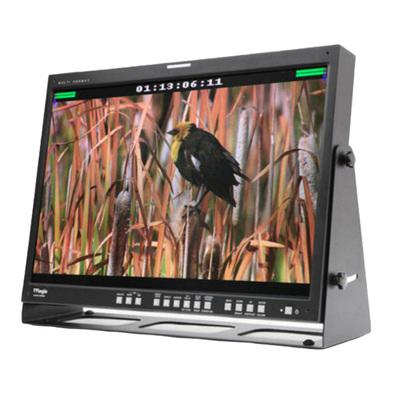
Multi Format Broadcast LCD Monitors Operation Manual 24-Inch Full HD LCD Grade 1 Monitor XVM-245W multi... -
Page 3: Table Of Contents
Contents ..................CAUTION CAUTION CAUTION ..................FEATURES FEATURES FEATURES ............NAME & FUNCTION OF EACH PART NAME & FUNCTION OF EACH PART NAME & FUNCTION OF EACH PART ..........MENU ORGANIZATION & ADJUSTMENT MENU ORGANIZATION & ADJUSTMENT MENU ORGANIZATION & ADJUSTMENT ................ -
Page 4: Caution
Caution ALWAYS USE SET VOLTAGE. AC 100 ~ 240V (1.6A/50~60HZ), DC 24V (TYP 3.2A) [ONLY XVM-245W] All operating instructions must be read and understood before the product is operated. These safety and operating instructions must be kept in safe place for future reference. - Page 5 Caution Upon completion of service or repair work, request the service technician to perform safety checks to ensure that the product is in proper operating condition. When mounting the product on a wall or ceiling, be sure to install the product according to the method recommended by the manufacturer.
-
Page 6: Features
Wide Screen compatible - Wide Screen for easier monitoring conditions. AC/DC compatible - The product may be powered by normal AC source, but also 24V DC(XVM-245W) Remote control function - Remote-controlled simply with cable connection without additional peripheral equipment attached to unit. -
Page 7: Name & Function Of Each Part
Name & Function of Each Part FRONT TALLY LY L MENU DOWN/BRIGHT UP/CONTRAST ENTER/VOLUME POWER CHROMA/PHASE/SCREEN SEL BLUE ONLY/MONO H/D DELAY / EXT.SYNC ANALOG MARKER MODE ASPECT UNDER SCAN [ANALOG] button/lamp - Used when ANALOG INPUT is selected. Sub Menu for analog input menu-selection appears. [MODE] button/lamp - Used when SDI INPUT A –>... - Page 8 Name & Function of Each Part [H/V DELAY & EXT. SYNC] button/lamp - Used when checking horizontal sync and vertical sync simultaneously. After applying Analog sync(CLK, H, V) check whether the SYNC is corresponding with SDI, Component, Composite modes. [BLUE ONLY / MONO] button/lamp - You may remove R(red) and G(green) from the input signal and play the screen only in B(blue) signal.
- Page 9 Name & Function of Each Part REAR REMOTE RS232 RS422 IN RS422 OUT CVBS1/Y/G/S-Y CVBS2/Pb/B CVBS3/Pr/R-S-C DVI-I HDMI(HDCP) SDI-A SDI-B ETHERNET EXT.SYNC AUDIO DC 24V IN ~AC IN [REMOTE] (RJ-45) - It provides connector to build connection with extra equipment for monitor control. [DVI-I IN] - When use our product at DVI display mode, DVI IN is input connector [RS-232]...
- Page 10 [Ethernet & USB] - Supports based on program download. [~ AC IN] - Used to supply AC power; 100V~240V input range. [DC 24V IN] - Used to supply DC power 24V(XVM-245W). [Information] - Input VIDEO connection method. Connector Composite Component...
-
Page 11: Menu Organization & Adjustment
Menu Organization & Adjustment The product may be controlled and set system-wise through OSD displayed on the screen. [1] Menu Organization Below is the organization of the product’s menu. [2] Menu Control You may control various functions using MENU, UP/DOWN and ENTER buttons on the front bottom of the monitor. -
Page 12: Menu Contents
Menu Contents Below is the description of each function of the menu. [1] PICTURE PART BRIGHT - This item controls the degree of brightness between MIN(-100) and MAX(100). CONTRAST - This item controls the contrast ratio between MAX(100) and MIN(-100). CHROMA - This item controls saturation between MAX(50) and MIN(-50). - Page 13 Menu Contents FOCUS ASSIST LEVEL - This item controls focus assist level. - Available values are between 0 ~ 100. Larger value means greater detail detection. - Focus assist color is presented when the difference between the border selections exceeds the selected value.
- Page 14 Menu Contents [2] VIDEO PART DITHERING - This item enables dithering to 10 bits. FILTER - This item selects set the filter ON for smoother transitions between colors. FAST MODE - This item minimize de-interlacing processing time delay. If user want to see without 1field time delay, use this mode.
- Page 15 Menu Contents [3] COLOR PART COLOR TEMP - This item controls color temperature and allows instant access to preset color temperature settings of 3200K, 5000K, 5600K, 6500K, 9300K and CUSTOM 1/2/3. - In CUSTOM1/2/3 mode, user can define custom RGB GAIN and BIAS values. GAIN RED - This item controls red color.
- Page 16 Menu Contents BIAS BLUE - This item adjusts black level to control blue color. - The value is selectable between Min(-50) and MAX(50). - Only available in CUSTOM 1/2/3 mode. COLOR COPY - This item is used to copy pre-stored color temperature settings into a CUSTOM 1/2/3 mode. - In CUSTOM mode, find and select the color temperature to be used as a starting point of custom color temperature.
- Page 17 Menu Contents [4] DISPLAY PART HD DISPLAY MODE - This item controls the display ratio of HD display. 16:9,1.85:1, 2.35:1 TIME CODE ENABLE - This item displays the time code.(VITC, LTC) * When multi screen mode, if the same input is displayed onto 2 screens, TIME CODE will be only seen on the first screen displaying the same input.
- Page 18 Menu Contents [5] GPI PART REMOTE (RJ-45) 1: Pin1 2: Pin2 3: Pin3 4: Pin4 5: Pin5 6: Pin6 7: Pin7 8: GND This product provides a REMOTE CONTROL mode. The user may connect RJ-45 jack to the REMOTE terminal on the rear of the unit and designate a function for each pin.
- Page 19 Menu Contents UMD DISPLAY - This item is display input UMD.(UMD,ANC, D-UMD(S-8C), D-UMD(S-16C), D-UMD(D-8C), OFF) UMD CHARACTER - This item is set input source UMD name. (Use Menu, Down, Up and Enter key.) D-UMD TALLY TYPE - This item selects the color of tally indication for D-UMD. (RED, DEFAULT, USER COLOR) TALLY1 COLOR - If D-UMD TALLY TYPE is set to USER COLOR, user can select the color of TALLY1.
- Page 20 Menu Contents [6] MARKER PART MARKER - This selects the marker type when the MARKER is displayed on the screen. MARKER may only be activated by pressing the MARKER button on the front of the monitor. Compatible MARKER types are as follows: MODE MARKER CLASS 16:9, 4:3, 4:3 ON AIR, 15:9, 14:9, 13:9, 1.85:1, 2.35:1, 1.85:1 &...
- Page 21 Menu Contents MARKER : 4:3 MARKER : 4:3 SAFETY AREA : 90% SAFETY AREA : 90% FIT MARKER : OFF FIT MARKER : OFF MARKER MAT - This item darkens the area of the outside of MARKER setting area. The degrees of darkness are between OFF(0) and (7).
- Page 22 Menu Contents [7] WAVEFORM PART WAVEFORM/VECTOR - This function sets the Waveform and Vectorscope. - This feature is available in SDI, COMPOSITE 1/2/3, S-VIDEO, COMPONENT modes. - Selectable features: OFF, WAVEFORM, VECTOR, YCbCr, MODE 1(WAVEFORM + VECTORY), MODE 2(VECTOR + Y/Cb/Cr), WIDE-Y - Displays on the bottom right of the screen and moves above the UMD, if UMD feature is selected.
- Page 23 Menu Contents WAVEFORM INTENSITY - This item controls the brightness of the WAVEFORM/VECTOR display. - Available values are between 0 ~ 30. The higher the number the brighter the waveform will be. WAVEFORM TRANS - This item controls the transparency level of the WAVEFORM/VECTOR. - Available values are OPAQUE and TRANS.
- Page 24 Menu Contents LVM-171WG RANGE ERROR - This item controls Y MAX, Y MIN, C MAX, C MIN, Y PICTURE BLINK, and C PICTURE BLINK. - Selected values in Y MAX, Y MIN, C MAX and C MIN indicates in WAVEFORM/VECTOR. Y MAX - This item sets the maximum luminance level.
- Page 25 Menu Contents [8] AUDIO PART AUDIO - This item controls audio level meter. If user want to see embedded audio signal, use this mode. - Audio level meter can select GROUP1 ~ GROUP4 or OFF. * When PBP screen mode, if the same input is displayed onto 2 screens, AUDIO LEVEL METER will be only seen on the first screen displaying the same input.
- Page 26 Menu Contents VOLUME - This item controls embedded audio volume between MIN (0) and MAX (30). Em. AUDIO LEFT - This item controls embedded audio channel for left audio out of internal speaker and [AUDIO OUT] in the back of the monitor. - Available values are between CH 1 ~ CH 16.
- Page 27 Menu Contents [9] SYSTEM PART USER CONFIG SET - This item saves monitor configuration. If user wants to save particular circumstance, use this mode. - This item saves monitor configuration. If user wants to save particular circumstance, use this mode. - This mode supports three users.
- Page 28 Menu Contents KEY LED - This item controls KEY LED ON/OFF. KEY DOWN MAPPING - User can select the function for DOWN button. - Selectable items: BRIGHT,VOLUME, FREEZE, WAVEFORM, TIMECODE, CC SEL, OUTPUT MODE, FAST MODE, DITHERING, FILTER,FORCE psf and UMD. KEY UP MAPPING - User can select the function for UP button.
-
Page 29: Other Functions
Other Functions [1] ANALOG MODE USAGE This product is capable of processing all input signals usable in ANALOG mode. The ANALOG input settings are as follows: 1. Press ANALOG button on the front of the product and activate the menu below. 2. - Page 30 Other Functions 3. Below are the di erent types of scan mode. - OVER SCAN : Zooms in/out of the image to 96% of its original size without changing the aspect ratio. - ZERO SCAN : Zooms in/out of the image without changing the aspect ratio. - UNDER SCAN : Zooms in/out of the image without changing the aspect ratio.
-
Page 31: Dvi Analog/Digital Support Resolution
Other Functions [3] ASPECT BUTTON 1. Two di erent aspect modes are available. When input signal is SDI or COMPONENT: 1) 4:3 mode: Cut left and right of the original image to t to 4:3 aspect ratio. 2) 16:9 mode: Stretches the image in “1) 4:3 mode” to t to 16:9 aspect ratio. (4) DVI SUPPORT RESOLUTION DVI ANALOG Resolution... - Page 32 Other Functions [5] PBP MODE USAGE 1. Use PBP key to change into PBP Screen. Then the last displayed multi screen appears. In Normal Screen(when an individual screen is not selected in multi mode), key function and OSD function apply for all display simultaneously. (PBP) (1:1 (FULL PICTURE) ** PBP: 2Picture...
- Page 33 Other Functions [6] INPUT LIMIT FOR ANALOG (MULTI MODE) 1. There is a limitation for Analog input in PBP Mode. (No limitation for SDI signals) 2. There are 3xBNC for the Analog inputs. So, if the BNCs or one of the BNCs are used for an Analog already, it cannot be used for another Analog input with the same BNC.
-
Page 34: Product Specification
Product Speci cation 1 x DVI - I DVI IN 3 x BNC Analog Input Input 2 x BNC SDI A/B Channel Input 1 x HDMI HDMI Input 1 x BNC EXT SYNC INPUT 3 x BNC Analog Output Output 2 x BNC SDI A/B Channel (Active Through Out) 1 x BNC... -
Page 35: Product Lineup
Product Lineup LVM-071W 1. LCD Resolution : 800 x 480 (15:9) 2. Color : 16.7M(true), 24bit 3. Contrast - 300 :1 4. Viewing Angle : H (130) / V (115) 5. Weight : 1Kg (2.2 lb) LVM-084 1. LCD Resolution : 1024 x 768 (4:3) 2. - Page 36 3. Contrast - 1200 :1 4. Viewing Angle : 178 5. Weight : 57Kg (125.66 lb) XVM SERIES XVM-245W 1. LCD Resolution : 1920 x 1200 (16:10) 2. Color : 1 Billion(true), 30bit 3. Contrast - 1000 : 1 4. Viewing Angle : 178...
- Page 37 Product Lineup LQM SERIES LQM-071W 1. LCD Resolution : 800 x 480 2. Color : 16.7M(true), 24bit 3. Contrast - 300 : 1 4. Viewing Angle : H (130) / V (115) 5. Weight : 1Kg (2.2 Ib) LQM-241W 1. LCD Resolution : 1920 x 1200 (16:10) 2.
-
Page 38: Optional Accessory
Optional Accessory 7” 9” ND Filter 17” 24” 40” 7” 9” 17” 24” External Filter Rack-Mountable Kit 46” 57” 7” 9” 17” 17” 7” 9” Tripod Ball Head V-Mount Hood-&-Handle 17” 24” 32” 40” 46” 57” Carrying Case RACK MOUNT ANY DISPLAY UP TO 24” 7 inch 9 inch 17 inch... - Page 40 FOR MORE INFORMATION PLEASE VISIT : http://www.tvlogic.co.kr Developed by #914 Namsung Plaza(Ace Techno Tower 9), 345-30 Gasan-dong, Geumcheon-gu, Seoul, 153-782, KOREA Tel : +82-2-2026-1333, Fax : +82-2-2026-1339, Email: support@tvlogic.co.kr...
Need help?
Do you have a question about the XVM-245W and is the answer not in the manual?
Questions and answers