Table of Contents
Advertisement
Advertisement
Table of Contents

Related Manuals for TV Logic LVM-171S


Summary of Contents for TV Logic LVM-171S
- Page 1 Multi Format LCD Monitor LVM-171S...
-
Page 3: Table Of Contents
Contents 1. Caution 2. Main Features 3. Controls & Functions 4. Menu Tree & Adjustment 5. Menu Operations [1] PICTURE [2] VIDEO [3] COLOR [4] GPI [5] MARKER [6] FUNCTION KEY [7] WAVEFORM & FOCUS [8] AUDIO [9] SYSTEM 6. Button Functions 7. -
Page 4: Caution
1. Caution Always use set voltage. ● • • If any of the following conditions occur, unplug AC 100 ~ 240V (50~60Hz) ● the power cord from the AC outlet, and DC 12V ● request a qualifi ed service person to perform repairs. - Page 5 1. Caution • • When relocating the product placed on a cart, • • When mounting the product be sure to install it must be moved with the utmost care. the product Sudden stops, excessive force and uneven according to the method recommended by fl oor surface can cause the product to fall from the manufacturer.
-
Page 6: Main Features
2. Main Features LVM-171S contains the following features: Compatible with various SDI(SD/HD/3G) Knob Control ● ● - Easy to adjust user confi guration using the signal formats control knob on the front of the monitor. - This product is compatible with various SDI... -
Page 7: Controls & Functions
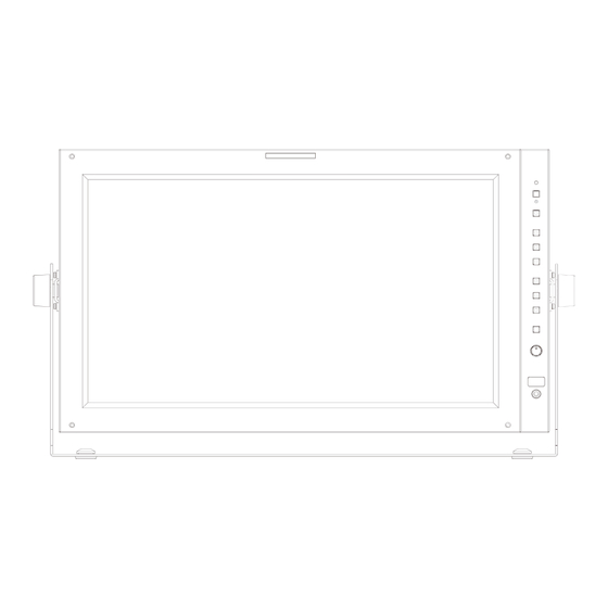
3. Controls & Functions LVM-171S : FRONT POWER SOURCE SCAN ASPECT MARKER FUNCTION/ FUNCTION SELECT MENU/EXIT KNOB(UP/DOWN/ENTER) USB(Firmware Update) AUDIO OUT LVM-171S : REAR REMOTE RS-422 IN RS-422 OUT CVBS1/Y/G/S-Y OUT CVBS1/Y/G/S-Y IN CVBS2/Pb/B OU T CVBS2/Pb/B IN CVBS3/Pr/R/S-C OUT... - Page 8 3. Controls & Functions FRONT [FRONT TALLY] [F1]~[F3] ● ● - Tally lamp that can be toggled in green - This Functions button is used to or red using the REMOTE(RJ-45) port or activate The feature selected in TVLogic’s management program(Observer). [F1]~[F3] Button.
- Page 9 3. Controls & Functions REAR [REMOTE] (RJ-45) [AUDIO IN] (Phone jack) ● ● - Provides connection to control - Audio input terminal for External Audio equipment(parallel switch) for external signal. monitor control. - Features of each pin can be changed. [AC IN] ●...
-
Page 10: Menu Tree & Adjustment
[3] Menu Control Sequence This Picture is the menu structure for Menu control sequence follows the order ● ● LVM-171S. below : 1. Press the MENU button to activate the OSD menu. 2. Move to a desired menu by rotating the Knob. - Page 11 4. Menu Tree & Adjustment [4] MENU TREE BRIGHTNESS GPI PIN 1~GPI PIN 8 CONTRAST GROUP ID CHROMA MONITOR ID PICTURE APERTURE DHCP ASPECT ID ADDRESS 3G FORMAT SUBNET MASK VIDEO VIDEO RANGE SELECT PORT NO. COLOR Temp. SETTING APPLY GAIN RED MARKER GAIN GREEN...
- Page 12 4. Menu Tree & Adjustment [4] MENU TREE KEY LED LEVEL METER SELECT KEY MAPPING F1~F5 LEVEL METER DISPLAY Function Key KEY LOCK LEVEL METER REFERENCE WAVEFORM DISPLAY LEVEL METER DECAY TIME WAVEFORM INTENSITY LEVEL METER SIZE AUDIO WAVEFORM TRANS LEVEL METER POSITION WAVEFORM COLOR VOLUME...
-
Page 13: Menu Operations
5. Menu Operations [1] PICTURE [2] VIDEO BRIGHT 3G FORMAT ● ● - Used to set the brightness level from -100 - Used to select input format of SDI 3G A/B to 100. support. (NORMAL MODE(AUTO - A 422 • Brightness can be adjusted by using the 10BIT_YCbCr 50/60P), A 444 10/12BIT_YCbCr, control knob on the front of the monitor. -
Page 14: Color
5. Menu Operations [3] COLOR COLOR SPACE ● - Used to select the color output format. - Available values are REC-709(sRGB), LUT SMPTE-C, LUT EBU, LUT D-CINEMA and NATIVE COLOR. GAMMA ● - Used to change the Gamma Curve between [2.2] and [2.4]. -
Page 15: Gpi
5. Menu Operations [4] GPI SDI A LVM-327W 1080/60i Menu PAGE I >> PAGE II COLOR TEMP 6500K Classifi - Settable Values GAIN RED cation GAIN GREEN GAIN BLUE BIAS RED BIAS GREEN NONE, BIAS BLUE ANALOG CHANNEL, COLOR COPY 6500K HDMI CHANNEL, SDI-A/B CHANNEL... - Page 16 5. Menu Operations [4] GPI GROUP ID ● - Used to group the monitors to control the monitors by group when the monitors are controlled by using RS-422/485 communication or Network. MONITOR ID ● - Used to set the ID of each monitor for the TVLogic control protocol or DYNAMIC UMD using RS-422/485 communication or Network.
-
Page 17: Marker
5. Menu Operations [5] MARKER FIT MARKER ● - Used to activate or inactivate the Fit Marker function. - When the Marker type is selected in the Marker menu, a border line of the Safety Area will be displayed inside the Marker. Images below show the diff erence between Fit Marker ON and OFF. -
Page 18: Function Key
5. Menu Operations [6] FUNCTION KEY [7] WAVEFORM & FOCUS KEY LED ● - Used to control the Key Lamp on the front of the monitor. F1 / F2 / F3 KEY MAPPING ● - User can select the function for the F1 / F2 / F3 button. - Page 19 5. Menu Operations [7] WAVEFORM & FOCUS LUMA(Y’) ZONE CHECK ● - Displays the Luma(Y’) level of the input image in colors. - Can select between [Color Pattern] or [Zebra Pattern]. - Each pixel’s Y’ analyzed and changed to a certain color or zebra pattern according to the Index on the right side of the screen.
- Page 20 5. Menu Operations [7] WAVEFORM & FOCUS RANGE ERROR ● - Used to set whether or not to activate Y MAX, Y MIN, C MAX, C MIN, Y PICTURE BLINK and C PICTURE BLINK functions. - The values of Y MAX, Y MIN, C MAX, C MIN are indicated in WAVEFORM/VECTOR.
-
Page 21: Audio
5. Menu Operations [8] AUDIO LEVEL METER SIZE ● - Used to control the size of the Audio Level Meters. - Available modes are SMALL, SMALL TRANS, NORMAL, NORMAL TRANS, LARGE and LARGE TRANS. - In SMALL, NORMAL and LARGE modes, the Audio Level Meter appears opaque. -
Page 22: System
5. Menu Operations [9] SYSTEM SET DEFAULT ● - Used to initialize OSD values to factory default. - Initializes the values to 0 of BRIGHT, CONTRAST, CHROMA, PHASE and APERTURE of the monitor. SW UPGRADE ● - Used to upgrade the fi rmware using the USB(Thumb drive). -
Page 23: Button Functions
6. Button Function [1] PBP(Picture-by-Picture) / PIP(Picture-in-Picture) PBP(PIP) Mode Select ● - Use the PBP button to change into PBP Screen. Available modes are as shown below. • In order to avoid confusion of terms, the PIP mode on the screen is collectively referred to as PBP. <PBP>... - Page 24 6. Button Function [2] USER Aspect Used to adjust the Width /Height display ● USER ASPECT ratio. 1. Press the [ASPECT] button on the front of WIDTH +1920 the monitor to acticate the [USER ASPECT] HEIGHT +1080 mode. 2. After the activation, press the Knob to begin controlling.
- Page 25 6. Button Function [3] Waveform / Vectorscope Waveform Y The Waveform/ Vectorscope function can ● ● - Displays the Luma(Y’) component of the be used only when the input signal is YUV. input signal into waveform. In the case of RGB input, Waveform RGB ●...
- Page 26 6. Button Function [4] Line Select (Waveform / Vector Scope) Used to select specifi c Vertical Line for Waveform / Vector. ● - It is available when the Line Waveform is activated. - To activate this feature, go to [Waveform]- [Waveform/Vector]-[Line Waveform]-[Select Line Position] and use the Knob to select a vertical line.
- Page 27 6. Button Function [5] Luma(Y’) Zone Check Color Pattern Type. Zebra Pattern Type. ● ● - Displays the Luma(Y’) level of the input - Displays the pixels with designated Luma(Y’) image in colors. levels with zebra pattern. - Y’ ≥ 100% : Pixels with higher Y’ level than - Y’...
- Page 28 6. Button Function [6] Focus Assist [7] Range Error Focus Assist function assigns a color to Pixels with Y’ or C’ levels exceeding the ● ● the pixels on the boundaries of the image designated levels of Y MAX, Y MIN, C MAX to inform the user to achieve the best and C MIN shall blink.
-
Page 29: Video Support Resolution
7. Video Support Resolution [1] SDI Mode Input Signal Signal Foramt (SD SDI) Interfaces 720x487 SD SDI (59.94i) YCbCr 4:2:2 10bit single link 720x576 (50i) Input Signal Signal Format (3G SDI) Interfaces 1920x1080 (60p/59.94p/50p) YCbCr 4:2:2 10bit 3G-SDI (A/B) single link 1920x1080 (30/29.97/25/24/23.98/ RGB 4:4:4 10bit / 12bit 30sF/29.97sF/25sF/24sF/23.98sF) - Page 30 7. Video Support Resolution [3] DVI-ANALOG Mode Resolution Frequency 640 X 480 60Hz, 75Hz 720 X 400 70Hz 800 X 600 60Hz, 72Hz, 75Hz 1024 X 768 60Hz, 70Hz, 75Hz 1366 X 768 60Hz / 75Hz [4] DVI-DGITAL GRAPHIC Mode Resolution Frequency 640 X 480...
-
Page 31: Product Specifi Cations
8. Product Specifi cations LVM-171S Size 16.5” Resolution 1920 X 1080 (16:9) Pixel Pitch 0.1905(H) X 0.1905(V) mm Color 1.06B Viewing Angle H: 178 degrees / V: 178 degrees Luminance of white 450 cd/ m (Center) Contrast Ratio 1400 : 1 Display Area 365.8(H) X 205.7(V) mm... -
Page 32: Optional Accessories
9. Optional Accessories Gold-Mount RACK MOUNT ANY DISPLAY UP TO 24” 8.4 inch 9 inc h 7 inch 15 inch 17 inch 21 inch 24 inch 32 Multi Format LCD Monitor... - Page 33 MEMO Multi Format LCD Monitor 33...
- Page 34 MEMO 34 Multi Format LCD Monitor...
- Page 36 FOR MORE INFORMATION PLEASE VISIT : http://www.tvlogic.tv 12F, ACE HIGH-END 8, 84 Gasan digital 1-ro, Geumcheon-gu, Seoul, 08590, KOREA TEL : +82-70-8668-6611, FAX : 82-2-6123-3201, E-mail : sales@ t vlogic.co.kr...
Need help?
Do you have a question about the LVM-171S and is the answer not in the manual?
Questions and answers