
Subscribe to Our Youtube Channel
Related Manuals for SunStar KM-2070P


Summary of Contents for SunStar KM-2070P
- Page 1 USER S MANUAL KM-2070P SERIES Electronically Controlled 1-Needle ZigZag Lock Stitch Machine (Mechanical Part)
- Page 2 1. Thank you for purchasing our product. Based on the rich expertise and experience accumulated in industrial sewing machine production, SUNSTAR will manufacture industrial sewing machines, which deliver more diverse functions, high performance, powerful operation, enhanced durability, and more sophisticated design to meet a number of user’s needs.
-
Page 3: Table Of Contents
CONTENT 1. Machine Sefety Regulations 2. Machine Specifications 3. Machine Configuration 1) Part Name of Machine 2) Internal Structure of Control Box 4. Machine Installation 1) Environment for Machine Installation 2) Electric Installation Environment 3) Safe Table Mounting of Machine 4) Installation of Presser Foot Lifter Pad 5) Adjustment of Presser Foot Lifter (group) Pad 6) Belt Cover Installation... - Page 4 18) Adjustment of the Device for Rasing Presser Foot Minutely 19) Method of Setting the Starting Point 8. Maintenance 9. In Case of Using Feed Dog Except Sunstar’ s One 10. Failure Causes and Countermeasures 11. Table Drawing 12. Guage Parts...
-
Page 5: Machine Sefety Regulations
Safety instruction on this manual are defined as Danger, Warning and Notice. If you do not keep the instructoins, physical injury on the human body and machine damage might be occurred. Danger : This indication should be observed definitely. If not, danger could be happen during the installation, conveyance and maintenance of machines. - Page 6 KM-2070P Series is made to sew patterns on fabrics and other similar material for 1-4) Machine Operation manufacturing. Follow the following indications when operating the machine. ⓐ Read through this manual carefully and completely before operating the machine. ⓑ Wear the proper clothes for work.
- Page 7 Caution mark is attached on the machine for safety. 1-6) Caution Mark Position When you operate the machine, observe the directions on the mark. Position of Warning Mark [ View from the right-front ] CAUTION 경 고 Do not operate without finger guard and safety devices.
-
Page 8: Machine Specifications
MODEL KM-2070P KM-2070P-7 Lock Stitch Stitch Type Max. 8mm/10mm (2 Step, 3 Step) ZigZag Width Stitch Length Max. 2.5mm Sewing Speed Max. 5,000 spm(4,000 spm at the time of shipment) SY 1965 Nm 70/10 or DP×5 #10 Needle DP Hook (Titanium Coated Inner Hook) : Hook Center is Offset... -
Page 9: Machine Configuration
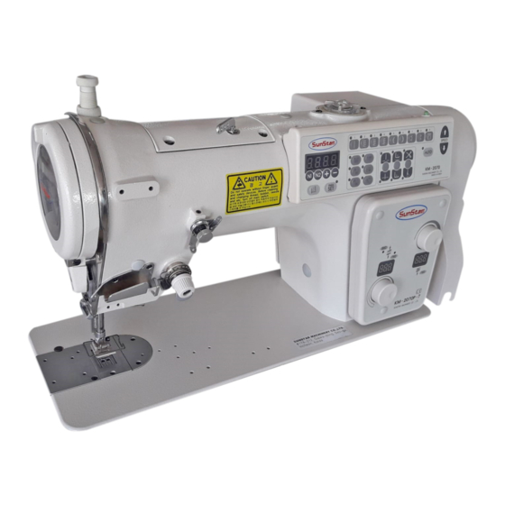
1) Part Name of Machine Face Plate Guard Thread Stand Operation Panel Belt Cover Feed Control Panel Power Switch Motor Control Box ※ Automatic Presser Foot Lifter (Option) -
Page 10: Internal Structure Of Control Box
2) Internal Structure of Control Box Step Motor Drive Board Digital Board Servo Motor Drive Board Power Board Transformer... -
Page 11: Machine Installation
1) Environment for Machine Installation A. In order to use safety, use in the environment as follows: Ambient Temperature for machine operation: 5° ~40° C(32° ~104° F) Ambient Temperature for machine reservation: -10° ~60° C(14° ~140° F) B. Humidity: within 45~80% (Relative Humidity) C. - Page 12 B. Insert head support rubber A①, and head support rubber B② to the corner of oil fan and then mount on the table. At this time, insert rising stitch support cap ③ on the hole ② of oil fan. ③ ①...
-
Page 13: Installation Of Presser Foot Lifter Pad
F. After connecting V belt, fully unfasten the fixing nut ①, ② to up and down, tension occurs to belt by self weight of motor ③. On this condition, fasten the fixing nut① first and the fixing nut ② tightly. ④... -
Page 14: Belt Cover Installation
6) Belt Cover Installation A. After inserting belt cover A① into sewing machine pulley and attach with joint screw③ (three screws). ② [ Fig. 8 ] B. Fasten the tapping screw⑤ (two) keeping belt cover C④ not to contact to belt cover A①. ①... -
Page 15: Power Voltage And Power Code Connection
■ Voltage change of 100~220V specification ■ Voltage change of 220V specification ■ Voltage change of 380~440V specification Trans former Model: KM-2070P-110 Trans former Model: KM-2070P-220 Trans former Model: KM-2070P-440 Location of Power Voltage... -
Page 16: Cable Connection To Control Box
9) Cable Connection to Control Box A. Internal Wiring of Control Box (Common in all types) Control Box Step Motor Driving Board Cooling Fan 14. Step Motor Driving Signal Cable 15. Servo Motor Driving Signal Cable Digital Board 16. Servo Motor Auxiliay Signal Cable Servo Motor Driving Board... -
Page 17: Exchanging The Fuse
15A : For the protection of main motor driving board power. 0.5A: For the protection of main motor driving board control power. 11) Head Earth Connection Please connect the header earth connection of KM-2070P as the following pictures. Header earth connection... -
Page 18: Preparations To Use The Machine
1) How to Fill Iubricating Oil A. Push the head backward. B. Fill lubricating oil up to the line marked “HIGH” . [ Note ] Supply the oil immediately when it gets lower to the line HIGH LOW marked “LOW” . [ Fig. -
Page 19: Bobbin Case Attachment Method
4) Bobbin Case Attachment Method ④ A. Adjust base line of thread take-up lever to meet with U mark of faceplate by turning sewing machine pulley. ③ B. Make the thread wornd to left and raise the bobbin and ② put into the bobbin case. -
Page 20: Upper Thread Passing Method
6) Upper Thread Passing Method After making base line of thread take-up lever to match with U mark on the face plate by turning the sewing machine pulley (Up stop location of need), hang the upper thread as shown in the figure. [ Fig. -
Page 21: Sewing Method
[ Note ] · Please attach protection device for safety. Using without attaching this device, it becomes cause of injury. · Please turn off the power in the following cases. Pedaling by mistake, the sewing machine operates and it becomes cause of injury. - Upper Thread passing - Exchange of bobbin or needle - When not using the sewing machine, or in case of being away from the sewing machine... -
Page 22: Machine Repairing Method
As the machine was set to the optimal status at the moment of factory shipping, do not adjust the machine Warning status optionally and when exchanging the parts, please change with the genuine parts that the company authorizes. 1) Thread Tension Adjustment A. -
Page 23: Presser Foot Pressure Adjustment
C. Adjustment of Thread Take-Up Spring Standard location of thread take-up spring is 6-8mm of distance to face of thread guide③ on condition that put ① ③ down the presser foot②. 1. Put down presser foot②. ④ 2. Unfasten the fixing screw④. 3. -
Page 24: Feed Dog Height Adjustment
4) Feed Dog Height Adjustment Standard height is 1mm when the feed dog① went up the most from needle plate upper face. A. Make the transfer value① to stop at the highest location ① by turning the sewing machine pulley. B. -
Page 25: Feed Dog Front And Back Adjustment
6) Feed Dog Front and Back Adjustment Gap front and back to the needle plate when the feed dog① ↓ moved closest to the user's side and when it moved to the be fixed ↑ most backward by turning the sewing machine pulley becomes regular. -
Page 26: Needle Bar Height Adjustment
8) Needle Bar Height Adjustment When the needle bar① came to the lowest point, height is from upper face of auxiliary needle plate② to the bottom of needle bar①, match to the height of timing gauge A③ of the ⑦ parts. -
Page 27: Needle And Hook Timing
9) Needle and Hook Timing A. Turn on the power switch. B. Press N1 and N2 key on the operation panel at the same time. (Refer to hook test function in 14-3) C. Take off presser foot, needle plate, auxiliary needle plate, feed dog, and needle plate spacer. -
Page 28: Synchronizer Adjustment
11) Synchronizer Adjustment → ← Pulley A. Mounting of synchronizer Pulley joint screw ⓐ Fix the synchronizer to back side of arm. ⓑ After setting the location of pulley that interval Upper between synchronizer and pulley becomes 1mm, shaft fasten pulley joint screw. Magnetic Holder Synchronizer [ Fig. -
Page 29: Lubrication Adjustment For Hook
12) Lubrication Adjustment for Hook When you replace the hook or change sewing speed, adjust lubrication amount of hook as the following order. ■ Confirmation of lubrication amount A. Perform no load operation over 1 minute at rotation number of sewing machine that actually sews. B. - Page 30 ■ Adjusting Upper Thread Feeding Wire After unfasten the fixing screw①, adjust remainder of upper thread by moving upper thread feeding wire②. In order to make the remainder short, move to arrow A direction and to make the remainder long, move to arrow B direction.
-
Page 31: Location Adjustment Of Thread Cutting Cam
14) Location Adjustment of Thread Cutting Cam Adjust as shown in the figure on condition that mess unit① is properly attached. ■ Left/Right Location Adjustment ② A. Lay down the sewing machine. B. Unscrew the fixing screw②. ④ C. Adjust by operating thread cutting operation crank ①... -
Page 32: Tension Adjustment Of Lower Thread Presser
15) Tension Adjustment of Lower Thread Presser After cutting thread, adjust tension when pulling out the thread holding by lower thread presser① to 0.03~0.08N(3~8gf) in case of filament thread (#60). A. Take off mess unit②. B. Draw out the mobile mess④ by moving handle③ and ⑤... -
Page 33: Gauge Parts
17) Gauge Parts In case of using presser foot, needle plate, and feed dog for other except 8mm of width, when operating the sewing machine, needle can contact to needle plate or needle can be broken. Hence, limit width as follows and exchange needle bar stopper. -
Page 34: Method Of Setting The Starting Point
KM-2070P B/T Starting Point Setting Flow As in the existing KM-2070P model, perform the setting of machine and install the control box. 1) Install the B/T motor and starting point sensor. 2) Connect the B/T motor and the starting point sensor cable. -
Page 35: Maintenance
Please execute trimming every day in order to maintain function of the sewing machine and use for long. Also in case that it was not used for long, use the sewing machine after trimming as followings. N N o o t t e e ·Turn off the power switch before work. -
Page 36: In Case Of Using Feed Dog Except Sunstar' S One
In case of using feed dog on the market, process the feed dog as shown in the figure. ※ If you use the feed dog without processing, rotary mess and fixed mess are damaged. R5.5 → ← → ←... -
Page 37: Failure Causes And Countermeasures
·Check the below points before you request the repair service. ·If the below process does not improve the status, turn off the power switch and ask to the purchase sales agent. Danger ·Turn off the power switch before work and pull of the plug. If you step on the pedal by mistake, the sewing machine starts operating and it becomes cause of injury. - Page 38 Order Failure Status Failure Cause Actions Using bent needle Needle replacement Using improper needle comparing to Needle replacement using thread Defective needle mounting Needle remounting Skip of sewing point Improper needle and hook timing Readjustment of needle and hook timing Interval of groove on needle and hook Readjustment of needle bottom dead point point is too large.
Need help?
Do you have a question about the KM-2070P and is the answer not in the manual?
Questions and answers