Table of Contents
Advertisement
S S U U N N S S T T A A R R M M A A C C H H I I N N E E R R Y Y C C O O . . , , L L T T D D . .
User's
Manual
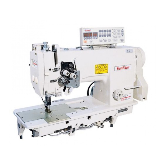
KM-757
High speed, two needle, drop
feed, needle feed, sewing
machine with automatic
thread trimmer.
KM- 797
High speed, two needle, drop
feed, needle feed, sewing
machine with automatic
thread trimmer for each
needle.
1. For proper use of the machine, thoroughly
read this manual before use.
2. Keep this manual in a safe place for future
reference in case the machine breaks down.
M M M M E E - - 0 0 5 5 0 0 6 6 2 2 9 9
Advertisement
Table of Contents


Need help?
Do you have a question about the KM-757 and is the answer not in the manual?
Questions and answers