Table of Contents
Advertisement
S S U U N N S S T T A A R R M M A A C C H H I I N N E E R R Y Y C C O O . . , , L L T T D D . .
User's
Manual
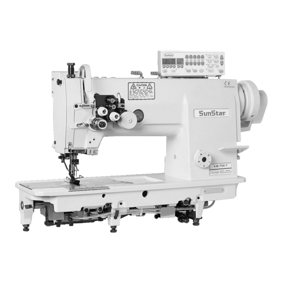
KM-750
High speed, two needle, drop
feed, needle feed, sewing
machine with automatic thread
trimmer.
KM- 790
High speed, two needle, drop
feed, needle feed, split needle
bar lock stitch M/C with
automatic thread trimmer
1. For proper use of the machine,
thoroughly read this manual before use.
2. Keep this manual in a safe place for
future reference in case the machine
breaks down.
M M M M E E - - 0 0 5 5 0 0 5 5 0 0 9 9
Advertisement
Table of Contents

Related Manuals for SunStar KM-750


Summary of Contents for SunStar KM-750
- Page 1 User’s Manual KM-750 High speed, two needle, drop feed, needle feed, sewing machine with automatic thread trimmer. KM- 790 High speed, two needle, drop feed, needle feed, split needle bar lock stitch M/C with automatic thread trimmer 1. For proper use of the machine, thoroughly read this manual before use.
- Page 2 1. Thank you for purchasing our product. Based on the rich expertise and experience accumulated in industrial sewing machine production, SUNSTAR will manufacture industrial sewing machines, which deliver more diverse functions, high performance, powerful operation, enhanced durability, and more sophisticated design to meet a number of user’s needs.
-
Page 3: Table Of Contents
Table of Contents Safety rules for machines ............................. 4 1. Specification 1) Specifications of the sewing machine ........................8 2) Specifications of the servo motor controller ......................9 3) Specifications of the clutch motor (for non-trimming type) ..................9 4) Peripheral automation devices (optional) ........................9 2. -
Page 4: Safety Rules For Machines
Safety Rules for Machines Safety labels in the manual are categorized into danger, warning and caution. Failure to follow the safety rules may result in physical injuries or mechanical damages. The safety labels and symbols are defined as follows. [ The meaning of the safety labels ] Danger Instructions here shall be observed strictly. - Page 5 1-1) Machine Only personnel with a full understanding of the safety rules should move the mobilization machines. The following directions must be observed when delivering the machines. ⓐ At least 2 persons should work together. ⓑ In case the machine should be transported, please wipe the oil covered on the machine to prevent the accident Danger 1-2) Machine...
- Page 6 1-4) Machine KM-750/790 series are manufactured for industry use to sew textiles and other similar Operation material. In case of running the machine, users should observe the following things. ⓐ Ahead of operating the machine, please read the manual and understand fully the details on its operation.
- Page 7 1-6) Position of “Cautions” is adhered to the machine for safety. Caution Mark In case of starting to run the machine, read the directions of “Cautions” carefully [Position of Caution Mark] CAUTION 경 고 Do not operate without finger guard and safety devices.
-
Page 8: Specification
Specifications 1) Specifications of the sewing machine Model No. Model Name KM-750 Two needle, drop feed, needle feed sewing machine (standard hook) KM-750-7 Two needle, drop feed, needle feed, sewing machine with automatic thread trimmer (standard hook) KM-750BL Two needle, drop feed, needle feed sewing machine (double hook) -
Page 9: Specifications Of The Servo Motor Controller
2) Specifications of the servo motor controller A. KM-750-7, 750BL-7 MODEL VOLT WATT HERTZ SC55-1B 1 phase 110V 550W 50/60 Hz SC55-2B 1 phase 220V 550W 50/60 Hz SC55-3B 3 phase 220V 550W 50/60 Hz B. KM-790-7, 790BL-7 VOLT WATT... -
Page 10: Installation
Installation Warning ▶ Installation of the machine should be performed by a trained engineer. ▶ Any electrical wiring must be performed by a qualified technician or agent. ▶ The machine weighs over 45kg. At least 2 persons should carry out the installing work. ▶... -
Page 11: Installation Of The Oil Fan
3) Installation of the oil fan Insert the projecting part of the oil fan ② into the respective Nail machine holes on the lower side of the table ①, and then push securely to the right. Fix the oil fan to the four fixing spots ③ using 4 nails. - Page 12 b) As can be seen on figure 5, make sure to supply oil into the oil holes marked in red and into each friction part, before moving the sewing machine. [Figure 5] c) Hook oil level check Check whether the amount of oil sprinkled from the hook for 10 seconds is as is on figure 6.
-
Page 13: Adjustment Of Belt Tension
5) Adjustment of belt tension After installing the motor, when the fixing nuts ①,② are unfastened to both sides with enough room, tension is created to the belt ④ due to motor ③ due to the motor’s own weight balance. At this moment, fasten the fixing nut ①... -
Page 14: Installation Of The Thread Stand
C. Lastly, fasten the belt cover “B”to the table, as can be seen in figure 10. [Figure 10] 8) Installation of the thread stand As can be seen in figure 11, fix the thread stand ① to the table using the washer and nut on the right. [Figure 11] 9) Location detector assembling and its control method (automatic trimming type) -
Page 15: Reverse Button Function
(2) Film adjustment of location detector A. For new model type (see figures 14, 15) Turn the pulley with hand so that the needle bar is placed where it starts rising from the lowest point. Unfasten the film fixing screw ① in figure 15, and for “DOWN”film A, align the film adjustment base line with the sensor adjustment base line, as can be seen in ⓚ. -
Page 16: Adjustment Of The Machine
Adjustment of the machine Caution ▶ In case of setting the needle, be sure to switch off the power supply. If the user presses on the step by mistake, the machine will start automatically, and this might lead to physical injuries. ▶... -
Page 17: Routing The Lower Thread
3) Routing the lower thread [Applicable Models] [Applicable Models] a) KM-750 a) KM -790 b) KM-750BL b) KM-790BL c) KM-750-7 c) KM-790-7 A. Insert the bobbin ① into the hook ②. A. Insert the bobbin① into the bobbin case②. For KM -790- B. -
Page 18: Routing The Upper Thread
Caution ▶ In case of taking up the upper thread, be sure to switch off the power supply. If the user presses on the step by mistake, the machine will start automatically, and this might lead to physical injuries. ▶ When using the clutch motor, remember that the motor revolves for a while even after switching off the power supply due to inertia. - Page 19 (2) Adjusting the lower thread tension Like in figure 25, turning the tension adjustment nut ① of the hook clockwise makes the lower thread tension stronger and counterclockwise makes it weaker. weak strong [Figure 25] (3) Adjusting the tension of thread take up lever spring A.
-
Page 20: Adjusting The Height And Pressure Of The Presser Foot
(5) Adjusting the auxiliary thread tension control Small assembly (automatic trimming type) Large As in figure 28, when the auxiliary thread tension adjustment nut ① is turned clockwise, the length of the thread after trimming is short. The other way makes the thread long. -
Page 21: Adjusting The Needle And Feed Dog Timing
8) Adjusting the needle and feed dog timing After removing the needle, lay down the machine on its back and remove the timing belt①. Turn the pulley② to align the highest position③ of the pulley’ s thread take up lever with the position ④. Then rotate the timing pulley ⑤ to align the bed base point ⑥... -
Page 22: Clearance Adjustment Between The Upper Side Of Hook Stopper And The Upper Side Of Needle Board Groove
(2) Adjusting the timing of hook edge and needle center crossing A. First, set the stitch length of (DIAL) KM-750, 750-7, Hook edge 790, 790-7 types at 2.5mm and KM-750BL, 750Bl- 7, 790BL, 790BL-7 types at 3.5mm. Adjust the hook gear fastening screw① so that like in figure 40, the hook edge fall exactly at the center of the needle center when the needle bar is raised 2.4mm from its... -
Page 23: Clearance Adjustment Between Hook And Opener
12) Clearance adjustment between hook and opener Loosen the opener fastening screw③ and adjust the opener ② to the right and left so that the distance between the hook ① and the opener ② is 0.2mm when the opener ② is pulled to its max towards the arrowed direction. - Page 24 (2) Trimming type (KM-790-7, 790BL-7) A. Button usage a) When stopping the left needle bar (when sewing left turn corner) Turn on the lamp by pressing the trimming direction button switch (left) ①. stop b) When stopping the right needle bar Turn on the lamp by pressing the trimming direction button switch (right) ②.
-
Page 25: Adjustment Of Safety Device
ⓔ Example When corner sewing is carried out after entering the following data, the resulting needlework will be as figure 39. Code No. Initial configuration What it means Whether or not semi-automatic corner work will Right needle up- Left needle up- be carried out Left needle up-stop stop position... -
Page 26: Adjusting Trimming Device
15) Adjusting trimming device (1) Adjusting the trimmer driving part A. Fixing the position of trimming cam (See figure 42) a) Turn the pulley with hand to place the needle bar ⑥at its lowest position. b) With the left side of the trimming cam① softly attached to the right side of the lower shaft medium bushing②, turn the cam to align the base point③... - Page 27 C. Fixing the position of the trimmer solenoid (ass’ y) (See figure 44) a) When the whole trimmer shake linkage① is in up position, that is, when it has come back to its original position after finishing trimming, the distance④ between the lower part of the roller② and the equal point of the trimming cam ③...
- Page 28 (3) Adjusting movable and fixed knives A. Adjusting the position of movable knife-edge and hook stopper a) When a movable knife ① passes the front side of the hook stopper ②, adjust the distance④ to be within 0.05~0.2 mm range like part ③. The upper surface of the movable knife-edge ⑥ should be set up 0.2mm below the upper side of hook stopper ⑤.
- Page 29 B. Adjusting movable and fixed knife (See figure 47) a) Like in figure 47, adjust the position of the fixed knife ③ so that the fixed knife right side edge② matches the movable knife inner side edge①. b) The initial assembling position of the movable knife ④ is where the movable knife-edge protrudes about 3 mm from the edge of the fixed blade.
- Page 30 C. Final fixing of the movable knife’ s initial position (See figure 48) ※ The standard initial assembling position of the movable knife ① is where the movable knife-edge protrudes about 3mm ③ from the fixed blade edge ② when the trimming action is finished, that is, when the movable knife is in its initial stop position.
-
Page 31: Replacing Movable Knife And Fixed Blade
E. Checkpoints on the assembling status of other trimming devices a) Check the starting point of the movable knife when the trimming action takes place ※ Operate trimming movement manually to check whether the thread take up lever is in the lowest or at least 2.5 mm raised level 0~2.5mm Point where the... -
Page 32: Adjustment Of Wiper
17) Adjustment of wiper about 0.3 mm about 0.3 mm about 0.3 mm [Figure 53] ⓐ Set the needle (at the needle position on the control after trimming) ⓑ Set the stitch length at dial “2” . ⓒ When pressing with hand as in the picture, the wiper edge ① should protrude about 0.3 mm from the needle edge. Loosen the four clamp screws ②... -
Page 33: Replacing Gauge Set For Needle Width
2. Remove the two needles 3. Disassemble the needle holder (※ turn it towards the arrowed direction for removal: KM-750 series) 4. Lift the presser bar lifter to raise the presser foot 5. Remove the presser foot 6. Remove the needle plate 7. -
Page 34: Cause Of Troubles And Troubleshooting
Cause of troubles and troubleshooting 1) Sewing machine troubleshooting Symptom Checkpoints Root cause Corrective action Needle is inserted into wrong position Reinsert the needle correctly and push in Direction and height of to its highest level. needle Needle is bent Change the needle Needle Needle breaks... - Page 35 Symptom Checkpoints Root cause Corrective action The height and distance between the Readjust the movable knife setting The gap between the movable knife and the hook do not match position movable knife and the hook Tension and contact of movable and Correct the tension adjustment and Check the tension of fixed knives are bad...
Need help?
Do you have a question about the KM-750 and is the answer not in the manual?
Questions and answers