Table of Contents
Advertisement
Quick Links
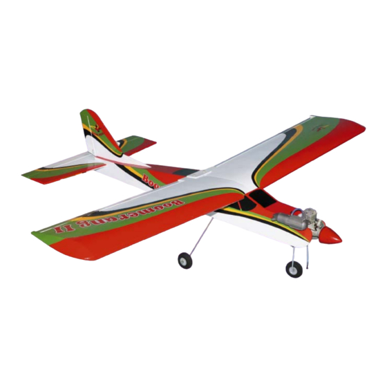
SPORTS TRAINER - ENGINE SIZE.40 - .46 - 2STROKE
Hand-made Almost Ready to Fly R/C Model Aircraft
Specifications
Wing span ____________________________ 155cm.
Wing area _________________________ 3950 sq cm .
Approximate flying weight _______________ 2.6-2.8kg.
Recommended engine size 0.40-0.46 cu. ins 2-stroke.
Recommended R/C __________ 4 channels minimum.
Flying skill level ___________________ Sports Trainer.
Electric conversion: optional
Kit features.
•
Ready-made—minimal assembly & finishing required.
•
Ready-covered—including decals, trim & covering.
•
Factory-installed pushrod.
•
Factory-pinned & glued control surface hinges for ultimate safety.
•
Comprehensive hardware pack including wheels, tank, spats,undercarriage& spinner.
•
Photo-illustrated step-by-step Assembly Manual.
ASSEMBLY MANUAL
Additional items required.
Engine.
4 Channels or greater Radio Control system.
Glues.
Tools.
Starting Equipment.
Made in Vietnam.
Advertisement
Table of Contents

Subscribe to Our Youtube Channel
Related Manuals for Seagull Models Boomerang 40


Summary of Contents for Seagull Models Boomerang 40
- Page 1 SPORTS TRAINER - ENGINE SIZE.40 - .46 - 2STROKE Hand-made Almost Ready to Fly R/C Model Aircraft ASSEMBLY MANUAL Specifications Additional items required. Wing span ____________________________ 155cm. Wing area _________________________ 3950 sq cm . Engine. Approximate flying weight _______________ 2.6-2.8kg. 4 Channels or greater Radio Control system.
-
Page 2: Instruction Manual
Flying the Boomerang 40 is simply a joy. This instruction manual is designed to help you build a great flying aeroplane. Please read this manual throughly before starting assembly of your Boomerang 40 . Use the parts listing below to identify all parts. -
Page 3: Hinging The Ailerons
C/A glue. fore gluing! This will ensure proper 1) Carefully remove the aileron from one assembly as the Boomerang 40 is of the wing panels. Note the position of the made from natural materials and hinges. -
Page 4: Hinging The Elevator
BOOMERANG 40. Instruction Manual. Epoxy. 4) Deflect the aileron and completely 5) Turn the wing panel over and deflect the saturate each hinge with thin C/A glue. The aileron in the opposite direction from the ailerons front surface should lightly contact the opposite side. -
Page 5: Hinging The Rudder
BOOMERANG 40. Instruction Manual. 2) Remove the brace when satisfied with HINGING THE RUDDER. its fit ineach wing half. Coat both sides of one half of the dihedral brace with 30 minute epoxy. Glue the rudder hinges in place using the same techniques used to hinge the ailerons. - Page 6 BOOMERANG 40. Instruction Manual. Carefully apply masking tape around 3. While holding the servo mount firmly the top and bottom edge of the root rib of each in place, trace around it using a pen. wing half to protect them from damage caused by epoxy.
-
Page 7: Installing The Aileron Servo
BOOMERANG 40. Instruction Manual. INSTALLING THE AILERON SERVO. Install the aileron servo into the servo mount, with the output shaft towards the lead- ing edge of the wing, using the wood screws provided with your radio system. Drill 1/16” pilot holes through the mount before installing the screws. -
Page 8: Installing The Nose Gear Wheel
BOOMERANG 40. Instruction Manual. INSTALLING THE NOSE GEAR WHEEL. Pen. Plastic trap. 4. Insert the main gear wire into the mounting slot. 5. Remove the two straps and the gear wire. Drill four 3/32” pilot holes into the fuse- lage for the wood screws. - Page 9 BOOMERANG 40. Instruction Manual. FUEL TANK. INSTALLING THE STOPPER ASSEMBLY. 1. Using a modeling knife, carefully cut 4. Carefully heat the vent tube using a off the rear portion of one of the two nylon tubes heat gun or lighter to permanently set the leaving 1/2”...
-
Page 10: Installing The Fuel Tank
BOOMERANG 40. Instruction Manual. Fuel tank. Top of tank. Vent tube. Fuel fill tube. Fuel tank. Fuel pickup tube. C/A glue. INSTALLING THE FUEL TANK. You should mark which tube is the vent and which is the fuel pickup when you attach Vent tube. -
Page 11: Mounting The Engine
BOOMERANG 40. Instruction Manual. Elevator servo. Trim and cut. Rudder servo. Throttle servo. THROTTLE SERVO ARM INSTALLATION. Install adjustable servo connector in the servo arm as same as picture below: Loctite secure. Adjustable Servo connector. Servo arm. Switch. Nut. MOUNTING THE ENGINE. -
Page 12: Nose Gear Installation
BOOMERANG 40. Instruction Manual. 3mm X 15mm. Pushrod wire. 4. Remove the engine. Using an drill bit, drill the mounting holes through the engine mount at the four locations marked. 1.5mm. NOSE GEAR INSTALLATION. 1.5mm. 5. Bolt the engine to the engine mount TOOLS REQUIRED using the four machine screws. - Page 13 BOOMERANG 40. Instruction Manual. Installing steering arm as follow. - Model size: .35-.45 size models - Motor: 35mm 830 rev per volt - Propeller: 10x7 - ESC: 50A - Lipo Batteries: 4cell 3200mA 2) Attach the electric motor box to the firewall suitable with the cross lines drawn on the electric motor box and firewall.
-
Page 14: Installing The Spinner
BOOMERANG 40. Instruction Manual. Blind nut. Blind nut. Battery. M4x70mm. Speed control. INSTALLING THE SPINNER. M3x15mm. Install the spinner backplate, propeller and spinner cone. The spinner cone is held in place using two 3mm x 12mm wood screws. The propeller should not touch any part of the spinner cone. -
Page 15: Horizontal Stabilizer
BOOMERANG 40. Instruction Manual. Slide the stabilizer into place in the pre- cut slot in the rear of the fuselage. The stabi- lizer should be pushed firmly against the front of the slot. 4. With the stabilizer held firmly in place, use a pen and draw lines onto the stabilizer where it and the fuselage sides meet. -
Page 16: Vertical Stabilizer Installation
BOOMERANG 40. Instruction Manual. 7. When you are sure that everything is aligned correctly, mix up a generous amount of 30 Minute Epoxy. Apply a thin layer to the top and bottom of the stabilizer mounting area and to the stabilizer mounting platform sides in the fuselage. -
Page 17: Control Horn Installation
BOOMERANG 40. Instruction Manual. 4. Slide the vertical stabilizer back in Control Horn. place. Using a triangle, check to ensure that the vertical stabilizer is aligned 90º to the hori- zontal stabilizer. Vertical Stabilizer. Horizontal 90º Stabilizer. Mounting Screws. Mounting Plate. - Page 18 BOOMERANG 40. Instruction Manual. Pen. Pen. 8mm. 8mm. Cut. Elevator. RUDDER PUSHROD HORN INSTALLATION. Rudder. Control horn. INSTALLING THE RECEIVER AND BATTERY. 1) Plug the five servo leads and the switch lead into the receiver. Plug the battery pack lead into the switch also.
- Page 19 BOOMERANG 40. Instruction Manual. Test fit the fin and the tail gear, to make Receiver. sure that everything fits properly. When you are happy with the fit, glue the fin permanently in place. See below picture how to assembly the tail-Dragger Conversion.
- Page 20 BOOMERANG 40. Instruction Manual. 2. Using the two landing gear straps as a guide, mark the locations of the four 3mm x 12mm mounting screws onto the fuselage sur- face. 3. The landing gear wire is held in place using two nylon landing gear straps and four 3mm x 12mm wood screws.
-
Page 21: Control Throws
We highly recommend setting up the your fingers on the masking tape and carefully lift the plane . Boomerang 40 using the control throws listed at right. We have listed control throws for both initial test flying/sport flying and aerobatic fly- Accurately mark the balance point on the top ing. - Page 22 2) Check every bolt and every glue joint control surface. Moving the adjustable con- in the Boomerang 40 to ensure that every- thing is tight and well bonded. trol horn toward the control surface will in- crease the amount of throw.
Need help?
Do you have a question about the Boomerang 40 and is the answer not in the manual?
Questions and answers