
Subscribe to Our Youtube Channel
Related Manuals for CTS FOS-3124-BAT-II Series


Summary of Contents for CTS FOS-3124-BAT-II Series
- Page 1 FOS-3124-BAT-II Series 20 PORTS 100/1000BASE-X SFP WITH 4 COMBO PORTS (10/100/1000BASE-T, 100/1000BASE-X SFP) UPLINK MANAGEMENT SWITCH User’s Guide Version 0.91...
- Page 2 Trademarks CTS is a registered trademark of Connection Technology Systems Inc All trademarks belong to their respective proprietor Contents subject to change without prior notice. Copyright Statement Connection Technology Systems Inc Copyright ©...
- Page 3 Revision History Version Date Description 0.90 20150209 First release 0.91 20150707 Specification Rearrangement...
-
Page 4: Table Of Contents
Table of Contents 1. INTRODUCTION ................... 5 1.1 The Managed Switch ................5 1.2 Front & Rear Panel ................... 7 1.4 Cable Specifications ................. 8 1.5 Network Management ................10 2. INSTALLATION ................... 11 2.1 Requirement ................... 11 2.2 Checking the Package Contents ............11 2.3 Install the Managed Switch .............. -
Page 5: Introduction
1. INTRODUCTION Thank you for choosing 20 PORTS SFP (100/1000BASE-X) WITH 4 COMBO PORTS UPLINK MANAGEMENT SWITCH. This Managed Switch is specifically designed to meet the emerging FTTX and Metro Ethernet requirements that can extend the transmission distance up to 80KM depending on SFP modules used. - Page 6 Key Features 19 inch, 1U high 20 x 100/1000Base-X ports IEEE 802.3/802.3u/802.3ab/802.3z compliance Support Auto-Sensing for fiber ports Support MDI/MDIX/Auto-Crossover SFP Slot 4 x 10/100/1000Base-T ,100/1000Base-X Combo ports IEEE 802.3ab/802.3z Support Auto-Negotiation (RJ-45) and Auto-Sensing (SFP) Support MDI/MDIX/Auto-Crossover RJ-45 or SFP Slot ...
-
Page 7: Front & Rear Panel
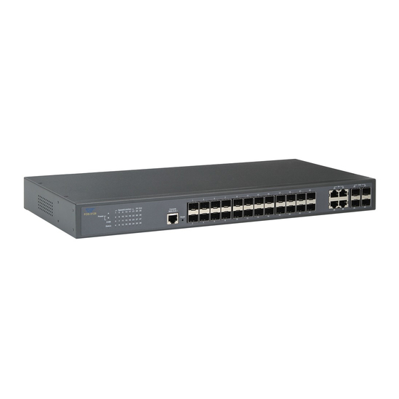
1.2 Front & Rear Panel Front Panel The front panel is configured as follows: Console port: An asynchronous serial console port supporting the RS-232 electrical specification. This is used to connect a console to the Managed Switch by using the supplied RS-232 to RJ-45 cable with the switch. This interface configuration is 9600, N, 8,1. -
Page 8: Cable Specifications
The rear panel is configured as follows: Power input and consumption: With AC Protector AC input: 200V-240V 50/60Hz DC input: 12V Power consumption: 85W (In charging state) Without AC Protector AC input: 100V-240V 50/60Hz DC input: 12V Power consumption: 85W (In charging state) Note: For BAT models, please be cautious that only DC12V Back-up Battery can be used. - Page 9 1000BASE-LX Single-mode fiber module (10km) 1000BASE-LH Single-mode fiber module (30km/50km) 1000BASE-ZX Single-mode fiber module (80km) SFP Transceiver for 1000BASE-SX Multi-mode fiber module (550m) SFP Transceiver for 1000BASE-LX Single-mode fiber module (10km) Mini-GBIC SFP Transceiver for 1000BASE-LH Single-mode fiber module (30km/50km) SFP Transceiver for 1000BASE-ZX Single-mode fiber module (80km)
-
Page 10: Network Management
1.4 Network Management This Managed Switch is Plug & Play compliant. Real-time operational status can be monitored through a set of LED indicators located in the front panel. Built-in management module also allows users to configure, control and monitor the system remotely. Following is a list of management options available in this Managed Switch: ... -
Page 11: Installation
2. INSTALLATION To properly install the Managed Switch, please follow the procedures listed below. These procedures are described below in separate sections. Installation Requirements Unpacking the Managed Switch Installing the Managed Switch Power on the Managed Switch ... -
Page 12: Install The Managed Switch
If any item is found missing or damaged, please contact your local sales representative for support or replacement. 2.3 Install the Managed Switch CAUTION To prevent any damage or failure of the Managed Switch, please DO NOT block the ventilation FAN holes. Use the following guidelines when choosing a place to install the Switch: ... -
Page 13: Power On
The Managed Switch can be mounted in an EIA standard-sized, 19-inch rack, which can be placed in a wiring closet with other equipment. Rack mounting brackets are provided to mount the Switch. Procedure 1. Plan the rack position. 2. Attach the mounting bracket on the switch’s side panels (one on each side) and secure them with the screws provided. - Page 14 Power Failure In the event of power failure, unplug the power that is plugged into the switch at the back of the device. When power is resumed, plug the power back to the switch. Please note that the Managed Switch has no ON/OFF switch. Therefore, the only way to power on or power off the switch is to connect or disconnect the power cord.
-
Page 15: Connect The Switch To Network
2.5 Connect the Switch to network Connect to Network This Managed Switch has 20 100/1000Mbps SFP ports and 4 combo ports on the front panel. These combo ports can be plug-in 10/100/1000Base-T copper or slide-in 100/1000Mbps SFP Fiber transceivers. The connection of the fiber port must be matched, i.e. -
Page 16: Operation
3. OPERATION The Managed Switch is Plug & Play compliant. Real-time operational status can be monitored through a set of LED indicators located in the front panel. A built-in management module provides users flexible interfaces to configure, control and monitor the complete system remotely. 3.1 LED Definitions Power A/B LED Color... - Page 17 Port LED 1~20 Color Operation No connection Green The link is up and the speed is in 100Mbps Link/ACT/Speed Orange The link is up and the speed is in 1000Mbps. Blinking Traffic is present. Green/Orange TP & F/O LED 21~24 Media Color Operation...
-
Page 18: Maintenance
4. MAINTENANCE This Managed Switch is easy to maintain. The procedures are suggested when you want to identify faults, perform hardware replacement and Firmware upgrade. 4.1 Fault Identification Identifying faults can greatly reduce the times required to find problem and solution. -
Page 19: Hardware Replacement Procedures
4.2 Hardware Replacement Procedures WARNING! The Managed Switch contains no user-serviceable parts. DO NOT, UNDER ANY CIRCUMSTANCES, open and attempt to repair it. Failure to observe this warning could result in personal injury or death from electrical shock. Failure to observe the above warning will immediately void any Warranty.
Need help?
Do you have a question about the FOS-3124-BAT-II Series and is the answer not in the manual?
Questions and answers