
Related Manuals for CTS FOS-5126 Series


Summary of Contents for CTS FOS-5126 Series
- Page 1 FOS-5126 Series 20 PORTS 100/1000BASE-X SFP + 4 COMBO PORTS (10/100/1000BASE-T, 100/1000BASE-X SFP) WITH 2 UPLINK Ports 10 Gbps SFP+ MANAGEMENT SWITCH User’s Guide Version 0.90...
- Page 2 Trademarks CTS is a registered trademark of Connection Technology Systems Inc All trademarks belong to their respective proprietor Contents are subject to change without prior notice.
- Page 3 Revision History Version Date Description 0.90 20151209 First release...
-
Page 4: Table Of Contents
Table of Contents 1. INTRODUCTION ................... 5 1.1 The Managed Switch ................5 1.2 Key Features .................... 6 1.3 Front & Rear Panel ................... 7 1.4 Cable Specifications ................. 8 1.5 Network Management ................9 2. INSTALLATION ................... 10 2.1 Requirement ................... 10 2.2 Checking the Package Contents ............ -
Page 5: Introduction
1. INTRODUCTION The Managed Switch is designed to meet the emerging FTTX & Metro Ethernet requirement. Its low profile appearance with 1U height and standard rack- mount size achieves the highest density within a single rack. When massive fiber ports need to be deployed, the Managed Switch provides the best performance and price ratio. -
Page 6: Key Features
1.2 Key Features 19 inch, 1U high 20 x 100/1000Base-X ports IEEE 802.3/802.3u/802.3ab/802.3z compliance Support Auto-Sensing for fiber ports Support MDI/MDIX/Auto-Crossover SFP Slot 4 x 10/100/1000Base-T ,100/1000Base-X Combo ports IEEE 802.3ab/802.3z Support Auto-Negotiation (RJ-45) and Auto-Sensing (SFP) Support MDI/MDIX/Auto-Crossover RJ-45 or SFP Slot ... -
Page 7: Front & Rear Panel
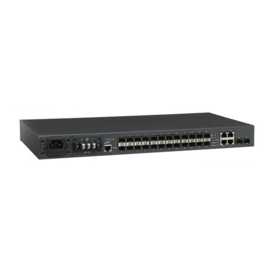
SNMP v1/v2c and network management SNMP Power-Down Trap Private, RFC-1213, RMON MIBs Port mirroring FTP, TFTP, HTTP server and client firmware upgrade **Coming Soon 1.3 Front & Rear Panel This section is divided into two parts based on different model. Front Panel ... -
Page 8: Cable Specifications
Power module and Connector: AC power connection: 100-240V , 50/60Hz DC power connection: 48VDC AC input x 1 DC input x 1 AC input x 2 DC input x 2 Rear Panel 1.4 Cable Specifications The following table contains various cable specifications for the Managed Switch. -
Page 9: Network Management
(30km/50km) SFP Transceiver for 1000BASE-ZX Single-mode fiber module (80km) 1.5 Network Management This Managed Switch is Plug & Play compliant. Real-time operational status can be monitored through a set of LED indicators located in the front panel. Built-in management module also allows users to configure, control and monitor the system remotely. -
Page 10: Installation
Please refer to the Network Management User’s Manual for the detailed management functions and required installation and operation procedures. 2. INSTALLATION To properly install the Managed Switch, please follow the procedures listed below. These procedures are described below in separate sections. ... -
Page 11: Install The Managed Switch
Documentation CD AC power cord (For AC power module only) If any item is found missing or damaged, please contact your local sales representative for support or replacement. 2.3 Install the Managed Switch CAUTION To prevent any damage or failure of the Managed Switch, please DO NOT block the ventilation FAN holes. - Page 12 Rack Installation WARNING! Please mount the Switch firmly in rack otherwise it may be fall and cause the system damage and possible injury to personnel. The Managed Switch can be mounted in an EIA standard-sized, 19-inch rack, which can be placed in a wiring closet with other equipment. Rack mounting brackets are provided to mount the Switch.
-
Page 13: Power On
2.4 Power ON The Managed Switch can be used with AC power supply 100-240 VAC, 50 – 60 Hz or DC power supply 48V. The power switch is located at the rear of the unit adjacent to the power connector. After the Managed Switch is turned on, the Power LED indicators should light in green and the FAN should spin. -
Page 14: Operation
3. OPERATION The Managed Switch is Plug & Play compliant. Real-time operational status can be monitored through a set of LED indicators located in the front panel. A built-in management module provides users flexible interfaces to configure, control and monitor the complete system remotely. 3.1 LED Definitions Front Panel Power A/B LED... - Page 15 Color Operation Green The device is in normal operation. The device is booting up. Orange Press the Reset button for 5~10 seconds (LED will turn to orange) and then release to restart the system. Status Press the Reset button for more than 10 seconds (LED will blink in Orange Blinking orange for 3 times) and then release to reset (back to factory settings) and restart the system.
-
Page 16: Maintenance
10G SFP+ LED 25~26 Media Color Operation Type No connection. Orange The link is up and the speed is in 1000Mbps. Blue The link is up and the speed is in 10Gbps. Traffic is present. Blinking Orange The port is in loop while slowly blinking on and off for 1 second respectively. -
Page 17: Hardware Replacement Procedures
Remote Check Users may check the Managed Switch through SNMP manager remotely. For detailed procedures, please refer to the network management User’s Manual. 4.2 Hardware Replacement Procedures WARNING! The Managed Switch contains no user-serviceable parts. DO NOT, UNDER ANY CIRCUMSTANCES, open and attempt to repair it. Failure to observe this warning could result in personal injury or death from electrical shock.
Need help?
Do you have a question about the FOS-5126 Series and is the answer not in the manual?
Questions and answers