Table of Contents
Advertisement
Quick Links
Advertisement
Table of Contents

Related Manuals for CTS FOS-3114 Series


Summary of Contents for CTS FOS-3114 Series
- Page 1 FOS-3114 Series 14-port L2 Managed Gigabit Fiber Switch User’s Guide Version:...
-
Page 2: Revision History
This is a Class A product. In a domestic environment, this product may cause radio interference in which case the user may be required to take adequate measures. Trademarks CTS is a registered trademark of Connection Technology Systems Inc. All trademarks belong to their respective proprietor Contents subject to change without prior notice. - Page 3 CTS Contact Information Headquarters/Manufacturer: ▓ Connection Technology Systems Inc. 18F-6, No.79, Sec.1, Xintai 5th Rd., Xizhi Dist., New Taipei City 221, Taiwan(R.O.C.) Tel: +886-2-2698-9661 Fax: +886-2-2698-3960 Sales Direct Line:+886-2-2698-9201 www.ctsystem.com Global Offices: ▓ Connection Technology USA Connection Technology Systems Japan 40538 La Purissima Way, Higobashi Bldg.
-
Page 4: Table Of Contents
Table of Contents Revision History ..................ii TABLE OF CONTENTS ................IV CHAPTER 1. INTRODUCTION ..........................2 1.1 O FOS-3114 ..............2 VERVIEW OF 1.2 K .................. 3 EATURES 1.3 F & R ................. 5 RONT ANELS 1.3.1 Front Panel ................5 1.3.2 Rear Panel ................ - Page 5 About this manual In this user’s guide, it will not only clearly introduce CTS FOS-3114 Managed Switch but tell you how to install this Managed Switch with detailed instructions. Organization of the Manual Chapter 1 “Introduction” describes the features of the Managed Switch ...
-
Page 6: Chapter 1. Introduction
Introduction Introduction CTS’s Managed Switch is designed to meet the emerging FTTX & Metro Ethernet requirements. Its low profile appearance with 1U height and the standard rack-mounted size achieve the highest density within a single rack. When massive fiber ports need to be deployed, the Managed Switch provides the best performance and price ratio. -
Page 7: Key Features
Introduction 1.2 Key Features 8.5 inch, 1U high 14 x 100/1000Base-X ports IEEE 802.3u/802.3z compliance Support Auto-Sensing for fiber ports SFP Slot Switching Features Store & forward switching Non-blocking switching fabric: 28Gbps Mac address table: 8K Packet buffer total 524K bytes VLANs support up to 2K VLAN Groups 802.1Q Tunneling (QinQ) VLAN Translation... - Page 8 Introduction Management Functions Console Telnet & SSH/CLI Web (HTTP & HTTPS) RADIUS for authentication SNMP v1/v2c/v3 and network management SNMP Power-Down Trap Private, RFC-1213, RMON MIBs Port mirroring FTP, TFTP, HTTP server and client firmware upgrade TACACS+ for authentication ...
-
Page 9: Front & Rear Panels
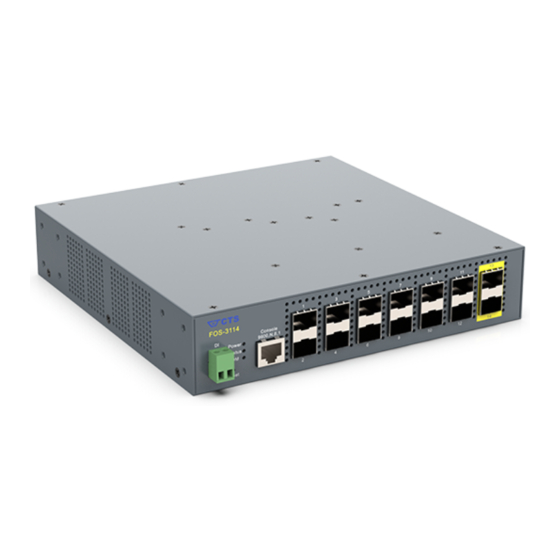
Introduction 1.3 Front & Rear Panels 1.3.1 Front Panel Figure 1-1. FOS-3114 Managed Switch Front Panel The interfaces on the front panel of the Managed Switch are described below: 14 x 100/1000Base-X SFP ports (Ports 1-14): Uplink Ports: Ports 13-14. Reset Button: ... - Page 10 Introduction LEDs: Includes Power LED, Status LED, COM LED, and LEDs of Fiber 1~14 ports. For more details on LEDs description, please refer to Section 1.4 LED Definitions. Publication date: October. 15, 2019 Revision 1.2...
-
Page 11: Rear Panel
Introduction 1.3.2 Rear Panel The Managed Switch provides one fixed power module. The type of power module is AC input. Figure 1-2. FOS-3114 Managed Switch Rear Panel The interface on the rear panel of the Managed Switch is described below: Power module and Connector: ... -
Page 12: Led Definitions
Introduction 1.4 LED Definitions The Managed Switch is Plug & Play compliant. The real-time operational status can be monitored through a set of LED indicators located in the front panel. Figure 1-3. LEDs of FOS-3114 Managed Switch Power LED The power status of the Managed Switch is indicated by the Power LED on the front panel of the device. -
Page 13: Cable Specifications
Introduction COM LED The console status is indicated by the COM LED on the front panel of the device. Color Operation Either the console port is not activated or no session exists. Lit when the console port is activated and the session Green exists. -
Page 14: Chapter 2. Installation
Installation Installation To properly install the FOS-3114 Managed Switch, please follow the procedures listed below. These procedures will be respectively described in detail in the following sections. Installation Requirements Checking the Package Contents Installing the Managed Switch ... -
Page 15: Installation Requirements
Installation 2.1 Installation Requirements Basic requirements for installation are as follows: Environmental conditions One power outlet Proper ventilation Proper isolation to electrical noise, radio, etc. Required SFP Transceiver Rack mounting tools 2.2 Checking the Package Contents Unpack the package carefully and check the package contents. -
Page 16: Installing The Managed Switch
Installation 2.3 Installing the Managed Switch You can install the FOS-3114 switch on a flat surface or mount it in a standard 19-inch network equipment rack. CAUTION To prevent any damage or failure of the Managed Switch, please DO NOT block the ventilation holes. -
Page 17: Rack Installation
Installation 2.3.2 Rack Installation Either you can install an 8.5-inch switch or two 8.5-inch switches in a standard 19-inch network equipment rack. In the following sections, we will take the FOS-3114 Managed Switch for example to separately demonstrate how to mount it or them in this size of rack space. WARNING! Please mount the Switch firmly in rack, otherwise it may fall and cause the system damage and possible injury to personnel. - Page 18 Installation Step 3. Then, tighten the screws with the screwdriver to secure each bracket. Step 4. Align the mounting holes in the brackets with the desired holes in the rack, and insert screws through each bracket and into the rack. Step 5.
-
Page 19: Install Two Fos-3114 Switches In A Rack Using Fos Combine Kit
Installation 2.3.2.2 Install Two FOS-3114 Switches in a Rack Using FOS Combine To install two sets of FOS-3114 in a single rack space, you need the 19-inch rack-mount kit as well as the FOS combine kit, supplied with the switch. Also follow the procedures listed below for step- by-step instructions to install your switches in this rack space: Step 1. - Page 20 Installation 2.4. On the left side of the switch, attach one ⼐-shaped fixed piece in the reverse direction by inserting the screws provided in the FOS combine kit through this fixed piece and into the mounting holes in the switch. (See Figure 2-3) 2.5.
- Page 21 Installation Step 5. Tighten the screws with the screwdriver to secure each middle mount. Step 6. Align the mounting holes in the regular brackets on both sides (the left side of the left switch and the right side of the right switch) with the desired holes in the rack, and insert the screws through each bracket and into the rack.
-
Page 22: Install A Single/Two Fos-3114 Switches In A Rack Using 19-Inch Rack- Mount Bracket
Installation 2.3.2.3 Install a Single/Two FOS-3114 Switches in a Rack Using 19- inch Rack-mount Bracket Besides the mounting methods we previously mentioned, to install one or two sets of FOS-3114 in a single rack space; alternatively, you can use the 19-inch rack-mount bracket supplied with the switch. - Page 23 Installation 19-inch Rack- mount Bracket Figure 2-6. Install the19-inch rack-mount bracket for two-switch mounting Step 3. Align the mounting holes on both sides of this 19-inch rack-mount bracket with the desired holes in the rack, and insert the screws through this bracket and into the rack. Step 4.
-
Page 24: Powering On The Managed Switch
Installation 2.4 Powering on the Managed Switch The Managed Switch can be used with AC power supply 100-240 V, 50–60 Hz, 0.4A~0.2A. After the Managed Switch is turned on, the Power LED indicators should light in green color. For more details about the power LED description, please refer to Section 1.4 LED Definitions. - Page 25 Installation 2.6.2 Removing SFP Modules To disconnect an LC/SC connector, use the following guidelines: 1. Press down and hold the locking clips on the upper side of the optic cable. 2. Pull the optic cable out to release it from the transceiver. 3.
-
Page 26: Chapter 3. Operation
Operation Operation A built-in management module of Managed Switch provides users flexible interfaces to configure, control and monitor the system remotely and locally. To know the further information about the operation of Managed Switch, please refer to FOS-3114 Network Management User’s Manual for the detailed management functions and required installation and operation procedures. - Page 27 Operation SNMP Management SNMP is also In-Band-Management and requires a network connection to the Managed Switch. The Managed Switch private Management Information Bases (MIB) is provided for SNMP-based network management program to configure, control and monitor the system. Web Management Web Management is done over the network.
-
Page 28: Chapter 4. Maintenance
Maintenance Maintenance This Managed Switch is easy to maintain. The procedures are suggested when you would like to identify faults, perform hardware replacement and do the firmware upgrade. 4.1 Fault Identification Identifying faults can greatly reduce the times required to find problem and solution. Users may perform local check or remote check to find the problems. -
Page 29: Remote Check
Maintenance 4.1.2 Remote Check Users may check the Managed Switch through SNMP manager remotely. For detailed procedures, please refer to the Network Management User’s Manual. 4.2 Hardware Replacement Procedures WARNING! The Managed Switch contains no user-serviceable parts. DO NOT, UNDER ANY CIRCUMSTANCES, open and attempt to repair it. - Page 31 18F-6, No.79, Sec.1, Xintai 5th Rd., XiZhi Dist., New Taipei City 221, Taiwan(R.O.C) Tel: +886-2-2698-9661 Fax: +886-2-2698-9662 Dir.Line:+886-2-2698-9201 www.ctsystem.com...
Need help?
Do you have a question about the FOS-3114 Series and is the answer not in the manual?
Questions and answers