Table of Contents
Advertisement
Quick Links
Download this manual
See also:
User Manual
Advertisement
Table of Contents

Related Manuals for Christie HD14K-M2


Summary of Contents for Christie HD14K-M2
- Page 1 Q u i c k S t a r t G u i d e 020-101941-01 M Series...
- Page 2 The warranty does not apply to any product where the serial number has been removed or obliterated. The warranty also does not apply to any product sold by a reseller to an end user outside of the country where the reseller is located unless (i) Christie has an office in the country where the end user is located or (ii) the required international warranty fee has been paid.
-
Page 3: Table Of Contents
Content Introduction ..........5 Purchase record and service contacts . - Page 4 Gamma ............22 Grayscale/Color Resolution .
-
Page 5: Introduction
Purchase record and service contacts Whether the projector is under warranty or the warranty has expired, Christie’s highly trained and extensive factory and dealer service network is always available to quickly diagnose and correct projector malfunctions. -
Page 6: Projector Models
The functions on the OSD can also be controlled using the Christie Serial Protocol, through a serial or Ethernet connection to the projector. The Web interface provides access to the menu system as a Virtual OSD (On-screen display) and to features that maintain the software and settings. -
Page 7: Key Features
Introduction • Line cord • Lens Mount Security Screw (M6x10mm long, Qty. 2) • Lens Mount Security Screw (5mm Hex, Qty. 1) • Warranty Card • Web Registration Form Key features • Up to 14,000 lumens • HD (1080p), SXGA+, or WUXGA resolution •... -
Page 8: Safety Warnings And Guidelines
Warning! Failure to comply with the following could result in death or serious injury. • All installation and maintenance procedures must be performed by a Christie qualified technician. Warning! Failure to comply with the following could result in death or serious injury. -
Page 9: Installation And Setup
Installation and Setup This section explains how to install, connect, and optimize the projector for delivery of superior image quality. Installing a projection lens The projection lens, shipped separately from the projector, must be installed prior to setting up the projector. - Page 10 Installation and Setup 3. Fully insert the assembly straight into the lens mount opening without turning and press with your hand as shown. 4. While holding the lens flat against the lens mount, rotate the lens clamp clockwise to lock the lens assembly in place.
-
Page 11: Positioning The Projector
Installation and Setup Positioning the projector Warning! Failure to comply with the following could result in death or serious injury. • Two people are required to safely lift and install the projector. Place the projector on a sturdy, level surface and position it so that it is perpendicular to the screen at a suitable distance. -
Page 12: Connecting The Line Cord
Installation and Setup Connecting the line cord Warning! Failure to comply with the following could result in death or serious injury. • Do not attempt operation if the AC supply and cord is not within the specified ratings. Use the line cord provided with the projector, or ensure you are using a line cord, power plug, and socket that meet the appropriate rating standards. -
Page 13: Mounting The Projector
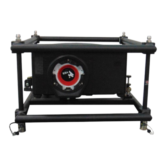
+/-15 degrees. Stacking projectors in a frame The M Series projectors can be stacked up to a maximum of three projectors high using the Christie stacking frame (118-100107-XX). 1. Turn the projector OFF and disconnect the AC power cord after the cooling fans have stopped. -
Page 14: Stacking Multiple Projectors
Installation and Setup 6. Use a 6 mm Allen key to tighten the six M8 bolts securing the base plate to the bottom of the projector. 7. When flying projectors overhead use the M8 safety point. Stacking multiple projectors The projectors can be stacked and hoisted in either an upright or inverted positions. Remove the locking pin from each stacking leg prior to alignment and ensure the four stacking legs are fully seated on the lower stacking frame. -
Page 15: Stacking Alignment
Installation and Setup The steel ball on the end of the pin keeps the pin from releasing inadvertently Table 1.1 3. When required, repeat steps 1 and 2 for the additional projectors in the stack. Stacking alignment Stacked projectors must be correctly aligned to one another so the resulting display is optimized. If hoisting the stack, do so first and then align. -
Page 16: Aligning The Image
Installation and Setup Aligning the image Only perform image alignment once the projector is fully assembled and powered up in its final location. Basic image alignment ensures the image reflected from the DMDs is parallel and well- centered with the lens and screen. This initial optical alignment is the foundation for optimizing images on the screen and must be completed before final boresight adjustments. -
Page 17: Aligning Boresight
Installation and Setup Aligning boresight 1. Display the boresight test pattern. a. Pressing the Test key on the remote keypad or use the built-in keypad and press the soft key that displays Test on the LCD display. b. Press the Up Arrow key to cycle to Boresight. c. - Page 18 Installation and Setup 4. Use a 5 mm hex driver to loosen three setscrews (A) on the lens mount. The setscrews must be backed out several turns to avoid contact with the inner lens mount plate. Cross-Hair Pattern Screw Locations Capscrew Setscrew 5.
-
Page 19: Powering Down The Projector
Installation and Setup 9. The original factory boresight can be approximately recovered, by positioning the three setscrews flush with the front face of the lens mount plate, and in contact with the inner lens mount plate. This may require adjusting both setscrews and cap screws. 10. -
Page 20: Projector Communications
Installation and Setup Projector communications Status LEDs Looking from the back of the projector, the LEDs represent, from left to right; Lamp 1, Lamp 2, Power, and Status. The LEDs display the colors as shown below: Projector states LEDS LED state Hard Boot All LEDs amber - means please wait Standby Mode... - Page 21 Installation and Setup Projector states LEDS LED state Note: A condition occurs on the first power on after a software upgrade, and is indicated by all the following: • The Status LEDS are cycling green • The LCD displays the warning Image Processor Upgrading •...
-
Page 22: Specifications
Specifications Specifications This section provides detailed projector specifications. Due to continuing research, detailed features are subject to change without notice. Pixel Format 1080p (H x V square pixels) 1920 x 1080 SXGA+ (H x V square pixels) 1400 x 1050 WUXGA (H x V square pixels) 1920 x 1200 Contrast... -
Page 23: Color Temperature
Specifications Color Temperature White Default CCT (without YNF) 7700 K ±2000 K 350W, 450W Lamp White YNF CCT (with YNF activation, electronically 6500 K ±1000 K corrected) Range of Adjustment 3200 K - 9300 K Tracking (deviation from normal over full range from 10 ±500 K max to 100 IRE) Stability (during rated lamp life) -
Page 24: Dual Link Dvi Input
Specifications Dual Link DVI Input Connectors One dual link DVI-I One analog 15-pin VGA Color spaces/signal types HDCP support A/D conversion 10 bits for single link DVI input 8 bits for dual link DVI inputs Frequency 165 Megapixels/s analog Video Decoder Input Connectors Two S-Video 4-pin miniature DIN Four BNC, 75 Ohm... -
Page 25: Power Requirements
Specifications Power Requirements Rated voltage 100 VAC – 240 VAC Rated Current (dual lamp operation) 450W 1080p / SXGA+ / WUXGA 15 A @ 100 VAC 370W 1080p / SXGA+ / WUXGA 12 A @ 100 VAC Line frequency 50/60 Hz AC Input Coupler 15 A, 250 VAC Type of connector... -
Page 26: Environment
Specifications Maximum shipping weight 40 kg (87 lb.) (includes packaging) Environment Temperature/Humidity/Altitude Operating temperature range 5 to 40ºC (41 to 104ºF) Storage temperature range -40 to 70ºC Humidity range 10% to 80%, non condensing Operating Altitude 10,000 ft. maximum Regulatory Safety •... -
Page 27: Marking
Specifications • EU Directive (2012/19/EU) on waste and electrical and electronic equipment (WEEE) and the applicable official amendment(s). • China Ministry of Information Industry Order No.39 (02/2006) on the control of pollution caused by electronic information products, the hazardous substances concentration limits (SJ/ T11363-2006), and the applicable product marking requirement (SJ/T11364-2006). - Page 28 Corporate offi ces Worldwide offi ces USA – Cypress Australia Eastern Europe and India Singapore ph: 714-236-8610 ph: +61 (0) 7 3624 4888 Russian Federation ph: +91 (080) 6708 9999 ph: +65 6877-8737 ph: +36 (0) 1 47 48 100 Canada –...
Need help?
Do you have a question about the HD14K-M2 and is the answer not in the manual?
Questions and answers