
Related Manuals for Advantech IDK-2108 Series


Summary of Contents for Advantech IDK-2108 Series
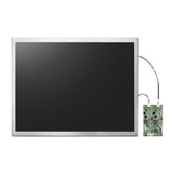
- Page 1 User Manual IDK-2108 Series 8.4" SVGA Ultra High Brightness Display Kit with LED Backlight...
- Page 2 No part of this manual may be reproduced, copied, translated or transmitted in any form or by any means without the prior written permission of Advantech Co., Ltd. Information provided in this manual is intended to be accurate and reliable. How- ever, Advantech Co., Ltd.
- Page 3 Whether your new Advantech equipment is destined for the labo- ratory or the factory floor, you can be assured that your product will provide the reliability and ease of operation for which the name Advantech has come to be known.
-
Page 4: Declaration Of Conformity
Declaration of Conformity This device complies with the requirements in part 15 of the FCC rules: Operation is subject to the following two conditions: This device may not cause harmful interference This device must accept any interference received, including interference that may cause undesired operation. - Page 5 Because of Advantech’s high quality-control standards and rigorous testing, most of our customers never need to use our repair service. If an Advantech product is defec- tive, it will be repaired or replaced at no charge during the warranty period. For out- of-warranty repairs, you will be billed according to the cost of replacement materials, service time and freight.
- Page 6 IDK-2108 User Manual...
-
Page 7: Table Of Contents
Contents Chapter Overview..........1 General Description .................. 2 Specifications .................... 2 1.2.1 LCD Panel..................2 1.2.2 LED Driver Board................2 1.2.3 Touchscreen (R series)..............2 1.2.4 Environment.................. 2 Mechanical Characteristics ............... 3 Functional Block Diagram ................. 3 Figure 1.1 Function Block Diagram ..........3 Touchscreen Driver................... - Page 8 Chapter Touchscreen & Touch Controller ..19 Touchscreen (Optional: for IDK-2108R Only) ......... 20 5.1.1 Touch Characteristics ..............20 5.1.2 Optical Characteristics..............20 5.1.3 Environmental Characteristics ............ 20 5.1.4 Mechanical Characteristics............20 5.1.5 Electronic Characteristics ............20 Touch Controller (Optional: for IDK-2108R Only) ........21 5.2.1 Touch Controller Characteristics ..........
-
Page 9: Chapter 1 Overview
Chapter Overview... -
Page 10: General Description
General Description IDK-2108 series is a Color Active Matrix Liquid Crystal Display composed of a TFT- LCD panel, a driver circuit, and backlight system. The screen format supports an SVGA screen of 800 x 600 pixels (H x V) at 16.2M colors (RGB 8-bit) or 262k colors (RGB 6-bit). -
Page 11: Mechanical Characteristics
Mechanical Characteristics IDK-2108N Series IDK-2108R Series Functional Block Diagram The following diagram shows the functional block of the 8.4 inch color TFT-LCD mod- ule: Figure 1.1 Function Block Diagram IDK-2108 User Manual... -
Page 12: Touchscreen Driver
Touchscreen Driver The touchscreen driver CD-ROM is in the accessories box and comes with the prod- uct. Absolute Maximum Ratings Absolute maximum ratings of the module is as follows: 1.6.1 Absolute Ratings of TFT LCD Module Item Symbol Min. Max. Unit Conditions Logic/LCD Drive Voltage... -
Page 13: Chapter 2 Electrical Characteristics
Chapter Electrical Characteristics... -
Page 14: Power Specifications
Power Specifications Input power specifications are as follows: Table 2.1: Power Specifications Symbol Parameter Min. Typ. Max. Unit Condition Logic/LCD [Volt] Drive Voltage Input Current - [mA] 64 Gray Bar Pattern (VDD=3.3V, at 60Hz) VDD Power [Watt] 64 Gray Bar Pattern (VDD=3.3V, at 60Hz) Rush Inrush Current -... -
Page 15: Backlight Driving Conditions
Backlight Driving Conditions Parameter guidelines for LED light bar driver are under stable conditions at 25°C (Room Temperature): Table 2.3: Backlight Driving Conditions Item Symbol Values Unit Condition Min. Typ. Max. LED Voltage Note 2 LED Current Note 2 LED Life Time 50,000 Note 1 Note 1: "LED life Time"... - Page 16 IDK-2108 User Manual...
-
Page 17: Chapter 3 Signal Characteristics
Chapter Signal Characteristics... -
Page 18: Pixel Format Image
Pixel Format Image The following figure shows the relationship between the input signal and LCD pixel format. Signal Description Table 3.1: Symbol Description Pin No. Symbol Description Power Supply, 3.3V (typical) Power Supply, 3.3V (typical) Vertical Reverse Scan Control. Low or NC -> Normal mode, Height ->... -
Page 19: The Input Data Format
The Input Data Format 3.3.1 SEL68 SEL68 = ”Low” or “NC” for 6-bit LVDS Input RxCLKIN RxIN1 RxIN2 RxIN3 SEL68 = “High” for 8-bit LVDS Input RxCLKIN RxIN1 RxIN2 RxIN3 RxIN4 Note 1: Please follow PSWG. Note 2: R/G/B data 7:MSB, R/G/B data 0:LSB IDK-2108 User Manual... - Page 20 Signal Name Description Remarks Red Data 7 Red Data 6 Red Data 5 Red Data 4 Red-pixel Data, For 8-bit LVDS input, MSB: R5; LSB:R0 Red Data 3 Red Data 2 Red Data 1 Red Data 0 Green Data 7 Green Data 6 Green Data 5 Green Data 4...
-
Page 21: Interface Timing
Interface Timing 3.4.1 Timing Characteristics Table 3.2: Timing Characteristics Signal Parameter Symbol Min. Typ. Max. Clock Timing Clock frequency 1/ T 33.6 39.8 48.3 Clock Period Vertical Active Vsync Timing Section Blanking Period 1056 1024 Horizontal Active Hsync Timing Section Blanking Note: Frame rate is 60 Hz. - Page 22 Power Supply VDD VALID LVDS Signal DATA Backlight On Power Sequence Timing Parameter Value Unit Min. Typ. Max. [ms] [ms] [ms] [ms] [ms] [ms] [ms] [ms] [ms] [ms] [ms] [ms] 1000 [ms] The above on/off sequence should be applied to avoid abnormal function in the dis- play.
-
Page 23: Chapter 4 Connector & Pin Assignment
Chapter Connector & Pin Assignment... -
Page 24: Tft Lcd Module
TFT LCD Module The physical interface described is for the connector on module. These connectors are capable of accommodating the following signals and consist of the following com- ponents listed. 4.1.1 Connector Table 4.1: Connector Connector Name / Description Signal Connector Manufacturer Connector Model Number STM-MSB24013P20HA or Compatible... -
Page 25: Led Driver Board
4.2.2 LED Driver Board 4.2.2.1 Specifications: Table 4.3: Specifications Symbol Characteristics Condition Min. Typ. Max. Unit Voltage Efficiency Vin=12V Input Iout=500mA Vout=8.9V Power Voltage 10.5 Current Output ≤ ≤ ± ± Current Accuracy 100mA Iout 500m Protection Thermal Shutdown °C Operating Junction °C Temperature... -
Page 26: Table 4.5: Output Connector Pin Definition
Table 4.4: Input Connector Pin Definition Dimming (PWM) 4.2.2.3 Output Connector Pin Definition Table 4.5: Output Connector Pin Definition Pin No. Pin Definition VLED- VLED+ 4.2.2.4 Dimensions Figure 4.1 Dimensions IDK-2108 User Manual... -
Page 27: Touchscreen & Touch Controller
Chapter Touchscreen & Touch Controller... -
Page 28: Touchscreen (Optional: For Idk-2108R Only)
Touchscreen (Optional: for IDK-2108R Only) 5.1.1 Touch Characteristics The touch panel is a resistance type that the customer uses with flat display like an LCD. Once the operator touches it using a resin pen with a round end or a finger, the circuit for the touch panel sends its coordinate points to the PC reading voltages at the contact points. -
Page 29: Touch Controller (Optional: For Idk-2108R Only)
Touch Controller (Optional: for IDK-2108R Only) 5.2.1 Touch Controller Characteristics The touch control board meets the latest Restriction of Hazardous Substances (RoHS) Directive. This touch panel controller provides optimal performance of your analog resistive touch panels for 4-wire models. It communicates with the PC sys- tem directly through a USB connector. -
Page 30: Specifications
5.2.3 Specifications USB Type Controller Circuit Board Dimensions 20mm x 75mm (0.79 inches x 2.95 inches) ---- (4-Wire) Power Requirements D.C.+5V (100mA typical, 50mV peak to peak maximum ripple and noise) Operating Temperature -25 to 85 °C Storage Temperature -55 to 150 °C Relative Humidity 95% at 60 °C Interface... - Page 31 Controller panel pin alignment Controller wafer pin alignment IDK-2108 User Manual...
- Page 32 IDK-2108 User Manual...
-
Page 33: Appendix A Optical Characteristics
Appendix Optical Characteristics... -
Page 34: Optical Characteristics
Optical Characteristics The optical characteristics are measured under stable conditions at 25°C (Room Temperature): Table A.1: Optical Characteristics Item Unit Conditions Min. Typ. Max. Note [degree] Horizontal (Right) CR = 10 (Left) Viewing Angle Vertical (Upper) CR = 10 (Lower) Luminance Uniformity 9 Points 2, 3... - Page 35 Note 2: 9-point position 90 % 50 % 10 % 10 % 50 % 90 % Note 3: The luminance uniformity of 9 points is defined by dividing the maximum luminance values by the minimum test point luminance Minimum Brightness of nine points Maximum Brightness of nine points Note 4: Measurement method The LCD module should be stabilized at a given temperature for 30 minutes to avoid...
- Page 36 Note 5: Definition of response time The output signals of the photo detector are measured when the input signals are changed from "Full Black" to "Full White" (rising time), and from "Full White" to "Full Black" (falling time), respectively. The response time is the interval between 10% and 90% of the amplitudes.
-
Page 37: Appendix B Handling Precautions
Appendix Handling Precautions... -
Page 38: Optical Characteristics
Optical Characteristics The optical characteristics are measured under stable conditions at 25°C (Room Temperature) Since the front polarizer is easily damaged, pay attention not to scratch it. Be sure to turn off the power supply when inserting or disconnecting from the input connector. - Page 39 IDK-2108 User Manual...
- Page 40 No part of this publication may be reproduced in any form or by any means, electronic, photocopying, recording or otherwise, without prior written permission of the publisher. All brand and product names are trademarks or registered trademarks of their respective companies. © Advantech Co., Ltd. 2012...
Need help?
Do you have a question about the IDK-2108 Series and is the answer not in the manual?
Questions and answers