Table of Contents
Advertisement
Quick Links
Advertisement
Table of Contents

Subscribe to Our Youtube Channel
Related Manuals for Advantech IDK-2121W


Summary of Contents for Advantech IDK-2121W
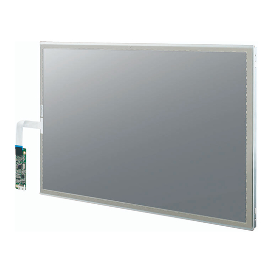
- Page 1 User Manual IDK-2121W Series TFT-LCD 21.5” FHD (LED Backlight)
- Page 2 No part of this manual may be reproduced, copied, translated or transmitted in any form or by any means without the prior written permission of Advantech Co., Ltd. Information provided in this manual is intended to be accurate and reliable. How- ever, Advantech Co., Ltd.
- Page 3 Whether your new Advantech equipment is destined for the labo- ratory or the factory floor, you can be assured that your product will provide the reliability and ease of operation for which the name Advantech has come to be known.
- Page 4 Because of Advantech’s high quality-control standards and rigorous testing, most of our customers never need to use our repair service. If an Advantech product is defec- tive, it will be repaired or replaced at no charge during the warranty period. For out- of-warranty repairs, you will be billed according to the cost of replacement materials, service time and freight.
-
Page 5: Table Of Contents
Table 4.2: Pin Assignment............22 Backlight Unit ..................22 4.2.1 Input Connector for LED Driver Board ........22 4.2.2 LED Driver Board................ 23 Table 4.3: Specification ............. 23 Figure 4.1 Dimension..............24 Appendix A Handling Precautions......25 Optical Characteristics ................26 IDK-2121W User Manual... - Page 6 IDK-2121W User Manual...
-
Page 7: Chapter 1 Overview
Chapter Overview... -
Page 8: General Description
General Description IDK-2121W series is a Color Active Matrix Liquid Crystal Display composed of a TFT- LCD panel, a driver circuit, and backlight system. The screen format is intended to support the FHD (1920(H) x 1080(V)) screen and 16.7M colors (RGB 8-bits data). All input signals are dual LVDS interface. -
Page 9: Optical Characteristics
Before measuring, the LCD module should be turn on 30 minutes at room tempera- ture. In order to stabilize the luminance, the measurement should be executed after lighting Backlight for 30 minutes in a stable, windless and dark room. IDK-2121W User Manual... - Page 10 ), respectively. The response time is interval between the 10% and 90% (1 frame at 60Hz) of amplitudes. = 16msec (typ.) Note 5: Color chromaticity and coordinates (CIE) is measured by TOPCON SR-3 Note 6: Central luminance is measured by TOPCON SR-3 IDK-2121W User Manual...
- Page 11 YA = Luminance of measured location without gray level 0 pattern (cd/m2) YB = Luminance of measured location with gray level 0 pattern (cd/m2) Note 9: Test Patern: subchecker pattern measured by TOPCON SR-3 Method: Record dB value with TRD-100 IDK-2121W User Manual...
-
Page 12: Functional Block Diagram
Functional Block Diagram The following diagram shows the functional block of the 21.5 inches Color TFT-LCD Module: Figure 1.1 Function block diagram IDK-2121W User Manual... -
Page 13: Absolute Maximum Ratings
[°C] Storage Humidity [%RH] Note 1: Within Ta (25 °C Note 2: Permanent damage to the device may occur if exceeding maximum values Note 3: For quality performance, please refer to AUO IIS (Incoming Inspection Stan- dard). IDK-2121W User Manual... -
Page 14: Outline Dimension
Outline Dimension 1.6.1 IDK-2121WR-K2FHA2E Front View Rear View IDK-2121W User Manual... -
Page 15: Idk-2121Wn-K2Fha2E
1.6.2 IDK-2121WN-K2FHA2E Front View Rear View IDK-2121W User Manual... - Page 16 IDK-2121W User Manual...
-
Page 17: Chapter 2 Electrical Characteristics
Chapter Electrical Characteristics... -
Page 18: Tft Lcd Power Consumption
At 75Hz IRush Inrush Current Note 1 VDDrp Allowable Logic/ [mV] p-p VDD= 5.0V, All white LCD Drive Ripple Pattern At 75Hz Voltage Note1 Measurement condition: The duration of raising time of power input is 47us. IDK-2121W User Manual... -
Page 19: Signal Electrical Characteristics
950 mA. Note2 The LED driving condition is defined for each LED module.(10 LED Serial). Note3 The variance of LED Light Bar power consumption is 10%. Calculator value for reference (IL x VL x 2 = PLED) IDK-2121W User Manual... - Page 20 IDK-2121W User Manual...
-
Page 21: Chapter 3 Signal Characteristics
Chapter Signal Characteristics... -
Page 22: Pixel Format Image
Positive LVDS differential clock input (Odd clock) RxO3- Negative LVDS differential data input (Odd data) RxO3+ Positive LVDS differential data input (Odd data) RxE0- Negative LVDS differential data input (Even data) RxE0+ Positive LVDS differential data input (Even data) Power Ground IDK-2121W User Manual... - Page 23 No connection (for AUO test only. Do not connect) No connection (for AUO test only. Do not connect) Power +5V Power +5V Power +5V Note1: Input signals of odd and even clock shall be the same timing. Note2: Please follow VESA. IDK-2121W User Manual...
-
Page 24: The Input Data Format
The Input Data Format Note1: Normally DE mode only. VS and HS on EVEN channel are not used. Note2: Please follow VESA. Note3: 8-bit in IDK-2121W User Manual... -
Page 25: Interface Timing
Clock Frequency 1/ TClock Frame Rate Frequency 1/Tv Period 1088 1120 2047 Vertical Active 1080 1080 1080 T_line Section Blanking Period 1034 1060 2047 Horizontal Active T_clock Section Blanking 1087 Note: DE mode. 3.4.2 Input Timing Diagram IDK-2121W User Manual... -
Page 26: Power On/Off Sequence
Signals from any system shall be Hi-Z state or low level when VDD is off. Power Sequence Timing Value Parameter Unit Min. Typ. Max. [ms] [ms] [ms] [ms] [ms] [ms] [ms] [ms] [ms] [ms] [ms] [ms] 1000 [ms] IDK-2121W User Manual... -
Page 27: Chapter 4 Connector & Pin Assignment
Chapter Connector & Pin Assignment... -
Page 28: Tft Lcd Module
The physical connector interface is described below. These connectors are capable of accommodating the following signals and components. 4.2.1 Input Connector for LED Driver Board Connector Name / Designation Interface Connector / Interface card Manufacturer JST or compatible Type Part Number PHR-6 or compatible IDK-2121W User Manual... -
Page 29: Led Driver Board
Current Accuracy 150mA Iout 950m Protection Thermal Shutdown °C Operation Junction °C Temperature Environment Operating Tempera- °C ture Storage Temperature + 85 °C Dimmer range Dimmer VH Dimmer (Note 1) Dimmer VL Dimmer Frequency ON/OFF Voltage Voff IDK-2121W User Manual... -
Page 30: Figure 4.1 Dimension
4.2.2.2 LED driver board dimension Figure 4.1 Dimension IDK-2121W User Manual... -
Page 31: Appendix A Handling Precautions
Appendix Handling Precautions... -
Page 32: Optical Characteristics
TFT Module. Otherwise the TFT Module may be damaged. Small amounts of materials having a no flammability grade are used in the LCD module. The LCD module should be supplied by power complying with the requirements of Limited Power Source (IEC60950 or UL1950) IDK-2121W User Manual... - Page 33 No part of this publication may be reproduced in any form or by any means, electronic, photocopying, recording or otherwise, without prior written permis- sion of the publisher. All brand and product names are trademarks or registered trademarks of their respective companies. © Advantech Co., Ltd. 2013...
Need help?
Do you have a question about the IDK-2121W and is the answer not in the manual?
Questions and answers