Table of Contents
Advertisement
Quick Links
Advertisement
Table of Contents

Subscribe to Our Youtube Channel
Related Manuals for KYLAND Technology KIEN1008G


Summary of Contents for KYLAND Technology KIEN1008G
- Page 1 KIEN1008G Industrial Ethernet Switch Hardware Installation Manual Kyland Technology Co., LTD. Publication Date: Oct. 2011 Version: V1.0 Customer Service Hotline: (+8610) 88796676 FAX: (+8610) 88796678 Website: http://www.kyland.cn E-mail: support@kyland.biz No.: 1.12.02.1029-0...
- Page 2 KIEN1008GIndustrial Ethernet Switch Hardware Installation Manual Disclaimer: Kyland Technology Co., Ltd. tries to keep the content in this manual as accurate and as up-to-date as possible.This document is not guaranteed to be error-free, and we reserve the right to amend it without notice.
- Page 3 Notice for Safety Operation This product performs reliably as long as it is used according to guidelines. Artificial damage or destruction of the equipment should be avoided. Read this manual carefully and keep it for future reference; Do not place the equipment near water sources or damp areas; Do not place anything on power cable and put the cable in unreachable places;...
-
Page 4: Table Of Contents
Contents 1. Packing List ......................5 2. Product Overview ....................5 3. Structure and Interface ..................5 3.1 Front Panel ..................... 5 3.2 Top Panel ......................7 4. Mounting ....................... 7 4.1 Mounting ......................7 4.2 Mounting Steps ....................8 5. -
Page 5: Packing List
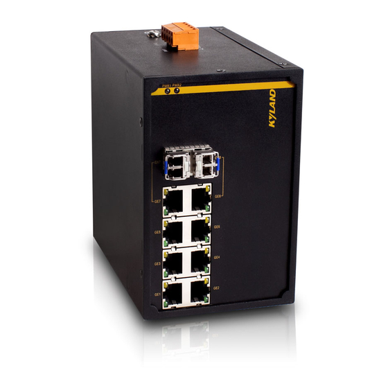
IP40 protection class and provides abundant Gigabit ports. 3. Structure and Interface 3.1 Front Panel KIEN1008G supports two kinds of product models. The interface is different for each product model. KIEN1008G-2GX/GE-6GE front panel is shown in Figure 1 below... - Page 6 6:(GE1-GE6)-six 10/100/1000Base-T(X) RJ45 ports 7:RJ45port Speed LED 8:RJ45portLink/ACT LED Figure 1 Front Panel 1 KIEN1008G-8GE front panel is shown in Figure 2 below 1: PWR1-Power 1 LED 2: PWR2-Power 2 LED 3:(GE1-GE8)-eight 10/100/1000Base-T(X) RJ45 ports 4:RJ45port Speed LED 5:RJ45portLink/ACT LED...
-
Page 7: Top Panel
3.2 Top Panel 1: Terminal block for power input 2: Screw hole for grounding Figure 3 Top Panel 4. Mounting 4.1 Mounting Dimension Drawing for DIN-Rail Mounting (Unit: mm) Figure 4 DIN-Rail Mounting... -
Page 8: Mounting Steps
4.2 Mounting Steps KIEN1008G DIN-Rail Mounting The specific steps are as follows: Step 1: Select the mounting position for KIEN1008G and ensure that there is adequate space. Step 2: Insert the top of the DIN-Rail into the spring-supported slot of the DIN-Rail connecting seat in the rear panel of KIEN1008G as seen below;... - Page 9 DIN-Rail and switch, as shown in arrow 1. Step 2: Pull the KIEN1008G up in the direction of arrow 2; meanwhile remove the device from the DIN-Rail along the direction of arrow 3.
- Page 10 Now the KIEN1008G should be firmly fixed to the wall or cabinet. Figure 8 Panel Mounting Remove KIEN1008G from wall or cabinet The specific steps are as follows: Step 1: Use a screwdriver to loosen 4 screws; move the device up to let screws into 4 holes with the diameter of 6.5mm (Ф6.5).
-
Page 11: Cable Connection
5. Cable Connection 5.1 10/100/1000Base-T(X) 10/100/1000Base-T(X) Ethernet RJ45 port can be connected to terminal equipment and network devices with straight-through cables or crossover cables. RJ45 connectors must be attached at both ends of cable. RJ45 port and pin number 8 7 6 5 4 3 2 1 Figure 10 RJ45 Port Pin distribution of 10/100/1000Base-T(X) -
Page 12: Combo Port
Figure 11 1000M Straight-through Cable Wiring 1000M crossover cable wiring Figure 12 1000M Crossover Cable Wiring 5.2 Combo port A Combo port is on the front panel, which consists of one RJ45 port and one gigabit SFP slot that accepts a modular SFP optical fiber transceiver. The RJ45... - Page 13 port and its related fiber port are both always connected but cannot be used simultaneously. For RJ45 port please refer to section 5.1 1000BaseSFP 1000Base SFP(1.25Gbit/s)Parameter Table Table 2 1000Base SFP(1.25Gbit/s) Parameter Table Property Multi Mode Single Mode Single Mode Single Mode Single Mode Type...
-
Page 14: Power
Wiring While wiring, first insert the SFP modular into the SFP slot in the device, and then plug the optical fiber into the SFP module. See Figure 14 Figure 14 SFP Gigabit Optical Fiber Transceiver Wiring 5.3 Power According to the power input requirements, use a 5.08mm-spacing terminal block to connect the power cable. -
Page 15: Grounding
Step 1: Take the power terminal block off KIEN1008G Step 2: Insert the power cable into the terminal block and fix the power cable Step 3: Put the terminal block back to KIEN1008G with the connected cable 5.4 Grounding Chassis grounding and power terminal grounding... - Page 16 There is a grounding screw on the top panel of the KIEN1008G, which is for chassis grounding. One end of the chassis grounding cable is connected with the grounding screw and the other end of the cable is reliably grounded. (The cross section area of chassis grounding cable should be more than 2.5mm...
-
Page 17: Led Indicators
Figure 18 Disconnect 18#AWG Yellow-green Line 6. LED Indicators Table 4 KIEN1008G LED Indicators State Description Power LEDs Power 1 connects and operates normally. PWR1 Power 1 disconnects or operates abnormally. Power 2 connects and operates normally. PWR2 Power2 disconnects or operates abnormally. -
Page 18: Product Models And Accessories
Blinking Network activities in the port (Green) No effective network connection in the port 7. Product Models and Accessories The specific configuration models of KIEN1008G are shown in Table 5 Table 5 KIEN1008G Configuration Table Model Description Power KIEN1008G-2GX/GE-6GE 2 1000M Combos Ports,... - Page 19 Power Requirements Power input: 12VDC (9~36VDC), 24VAC/DC (18~50VAC, 18~72VDC) Power terminal: 5-pin 5.08mm-spacing plug-in terminal block Power consumption: full load: KIEN1008G-2GX/GE-6GE: 8.5W(full load) KIEN1008G-8GE: 7.5W(full load) Physical Characteristics Housing:Metal,fanless Installation: DIN-Rail or Panel mounting Dimensions (W×H×D): 88mm×135mm×137mm Weight: 0.76Kg Environment Limits Operating Temperature: -40℃...
Need help?
Do you have a question about the KIEN1008G and is the answer not in the manual?
Questions and answers