
Related Manuals for KYLAND Technology KIEN7009


Summary of Contents for KYLAND Technology KIEN7009
- Page 1 KIEN7009/SICOM3009A/SICOM3306 Industrial Ethernet SwitchHardware Installation Manual Publication Date: Mar. 2015 Version: V1.1...
- Page 2 KIEN7009/SICOM3009A/SICOM3306 Industrial Ethernet Switch Hardware Installation Manual Disclaimer: Kyland Technology Co., Ltd. tries to keep the content of this manual as accurate and as updated as possible. This document is not guaranteed to be error-free, and we reserve the right to amend it without notice to users.
- Page 3 Notice for Safety Operation The product performs reliably as long as it is used according to the guidance. Artificial damage or destruction of the device should be avoided. Before using the device, read this notice carefully for personal and equipment safety. Please keep the manual for further reference.
- Page 4 Do not disassemble the device by yourself. When an anomaly occurs, contact our sales or technical support personnel. If any part is lost, contact our sales or technical support personnel to purchase the substitute. Do not purchase parts from other channels. ...
- Page 5 The following information applies when operating this device in hazardous locations: Suitable for use in Class I, Division 2, Groups A, B, C and D Hazardous Locations, or nonhazardous locations only. Cet appareillage est utilisable dans les emplacements de Classe I, Division 2, Groupes A, B, C et D, ou dans les emplacements non dangereux seulement.
-
Page 6: Table Of Contents
Contents 1 Product Overview .......................1 2 Structure and Interface .......................5 2.1 Front Panel ........................5 2.2 Top Panel ........................7 3 Mounting ..........................8 3.1 Dimension Drawing (Unit: mm) ..................8 3.2 Mounting Modes and Steps ..................9 3.2.1 DIN-Rail Mounting ....................9 3.2.2 Panel Mounting ....................10 4 Cable Connection ...................... -
Page 7: Product Overview
Web, Telnet, and console port. KIEN7009/SICOM3009A/SICOM3306 supports DIN rail mounting and panel mounting. KIEN7009 and SICOM3009A provides up to six 10/100Base-T(X) Ethernet ports and three 100Base-FX/100Base-TX ports. SICOM3306 provides up to six 10/100Base-T(X) Ethernet ports, two 100Base-FX Ethernet ports, and one 1000Base-X, 10/100/1000Base-T(X) SFP slot. - Page 8 Product Overview SC40=SC connector, 1310nm, 40km FC40=FC connector, 1310nm, 40km SC60=SC connector, 1310nm, 60km SC80=SC connector, 1550nm, 80km Ports without S or M: L2-L2 (24DCW, redundant power input, UL approved), PS1-PS2: power input L5-L5(12DCW, redundant power input) Table 2 SICOM3009A Models Models SICOM3009A-Ports-Connector-PS1-PS2 Code definition...
- Page 9 Product Overview L2-L2 (24DCW, redundant power input, UL approved), PS1-PS2: power input L5-L5(12DCW, redundant power input) Table 3 SICOM3306 Models Models SICOM3306-Ports-Connector-PS1-PS2 Code definition Code option 1GX2S6T, 1GX2M6T, 3GX6T, 2GX6T, 1GX8T Note: 1GX2S6T: one 1000Base-X, 10/100/1000Base-T(X) SFP slot; two 100Base-FX Ports: GX, S/M, T ports, single mode;...
- Page 10 Product Overview Note: For the product information listed in the preceding table, we reserve the right to amend it without notice to users. To obtain the latest information, you can contact our sales or technical support personnel.
-
Page 11: Structure And Interface
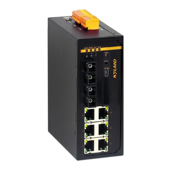
To keep ports clean and ensure switch performance, you are advised to purchase the port dustproof shield (optional). 2.1 Front Panel Front Panel of KIEN7009-3S/M-6T and SICOM3009A-3S/M-6T Figure 1 Front Panel of KIEN7009-3S/M-6T and SICOM3009A-3S/M-6T Table 4 Description of the Front Panel of KIEN7009-3S/M-6T and SICOM3009A-3S/M-6T Identifier Description PWR1 Power 1 LED... - Page 12 Structure and Interface Console Console port 100Base-FX Ethernet ports 100Base-FX Ethernet port LEDs (10) 10/100Base-T(X) Ethernet ports (11) 10/100Base-T(X) Ethernet port speed LED (yellow) (12) 10/100Base-T(X) Ethernet port connection status LED (green) Front Panel of SICOM3306-1GX-2S/M-6T Figure 2 Front Panel of SICOM3306-1GX-2S/M-6T Table 5 Description of the Front Panel of SICOM3306-1GX-2S/M-6T Identifier Description...
-
Page 13: Top Panel
Structure and Interface Reset Reset button Console Console port Gigabit SFP slot Gigabit SFP slot LED (10) 100Base-FX Ethernet ports (11) 100Base-FX Ethernet port LEDs (12) 10/100Base-T(X) Ethernet ports (13) 10/100Base-T(X) Ethernet port speed LED (yellow) (14) 10/100Base-T(X) Ethernet port connection status LED (green) 2.2 Top Panel Figure 3 Top Panel Table 6 Description of the Top Panel... -
Page 14: Mounting
Figure 5 Dimensions for Panel Mounting Caution: The preceding figure uses SICOM3009A-3S/M-6T as an example. The other models of KIEN7009/SICOM3009A/SICOM3306 have the same dimensions with SICOM3009A -3S/M-6T. As part of the heat dissipation system, the switch housing becomes hot during operation. -
Page 15: Mounting Modes And Steps
Mounting 3.2 Mounting Modes and Steps The device supports both DIN-rail mounting and panel mounting. Before installation, make sure that the following requirements are met. 1) Environment: ambient temperature (see 8 Basic Features and Specifications), ambient relative humidity (5% to 95%, non-condensing) 2) Power requirement: The power input is within the voltage range of the switch. -
Page 16: Panel Mounting
Mounting connecting seat is detached from the DIN rail. In this way, the device is removed from the DIN rail completely. Figure 7 DIN-Rail Dismounting 3.2.2 Panel Mounting Caution: To adopt panel mounting, you need to purchase the plate for panel mounting (optional). ... - Page 17 Mounting Figure 8 Panel Mounting Dismounting Step 1: Loosen the four screws with a screwdriver. Move the device upward until the four screws are in the Ф6.5 positions in the following figure. Then remove the plate for panel mounting from the four screws to detach the device from the wall or inner wall of the cabinet.
-
Page 18: Cable Connection
Cable Connection 4 Cable Connection 4.1 10/100Base-T(X) Ethernet Port 10/100Base-T(X) Ethernet port is equipped with RJ45 connector. The port is self-adaptive. It can automatically configure itself to work in 10M or 100M state, full or half duplex mode. The port can also adapt to MDI or MDI-X connection automatically. You can connect the port to a terminal or network device with a straight-through or cross-over cable. -
Page 19: 100Base-Fx Ethernet Port
Cable Connection Wiring Sequence Figure 11 Connection Using Straight-through/Cross-over Cable Note: The color of the cable for RJ45 connector meets the 568B standard: 1-orange and white, 2-orange, 3-green and white, 4-blue, 5-blue and white, 6-green, 7-brown and white, and 8-brown. 4.2 100Base-FX Ethernet Port 100Base-FX port is equipped with FC/ST/SC connector, and each port consists of TX (transmit) port and RX (receive) port. -
Page 20: 1000Base-X, 10/100/1000Base-T(X) Sfp Slot
Cable Connection Caution: A laser is used to transmit signals in fiber cables. The laser meets the requirements of level 1 laser products. Routine operation is not harmful to your eyes, but do not look directly at the 100Base-FX Ethernet port when the switch is powered on. 4.3 1000Base-X, 10/100/1000Base-T(X) SFP Slot 1000Base-X, 10/100/1000Base-T(X) SFP slot (Gigabit SFP slot): You can enable data transmission only after inserting an SFP optical/electrical module into the slot and... - Page 21 Cable Connection (transmit) port and an RX (receive) port. To enable communication between Device A and Device B, connect the TX (transmit) port of Device A to the RX (receive) port of Device B, and the RX (receive) port of Device A to the TX (transmit) port of Device B. The following figure shows the cable connection of the Gigabit SFP optical module.
-
Page 22: Gigabit Sfp Electrical Module
Cable Connection 4.3.2 Gigabit SFP Electrical Module Figure 16 Gigabit SFP Electrical Module How to Connect the Gigabit SFP Electrical Module Insert the SFP electrical module into the SFP slot in the switch, and then plug the RJ45 connector of the twisted pair into the SFP module. Figure 17 Connecting the Gigabit SFP Electrical Module 4.4 Console Port Caution:... -
Page 23: Grounding
Cable Connection Figure 19 Mini USB Connector The following table lists the pin definitions of the Mini USB connector. Table 9 Pin Definitions of the Mini USB Connector Mini USB Pin Definition VBUS Grounding USB Connector The following figure shows the pin numbers of the USB connector. Figure 20 USB Connector The following table lists the pin definitions of the USB connector. -
Page 24: Power Terminal Block
Cable Connection the end to the grounding screw and connect the other end to the earth firmly. Figure 21 Grounding Note: Cross-sectional area of the chassis grounding cable>2.5mm ;Grounding resistance<5. 4.6 Power Terminal Block There is a power terminal block on the top panel of the switch. You need to connect the power cable to the terminal block to provide power for the switch. - Page 25 Cable Connection Table 11 Pin Definitions of 5-Pin 5.08mm-Spacing Plug-in Terminal Block DC Definition AC Definition PWR1: + PWR1: L PWR1: - PWR1: N PGND PGND PWR2: - PWR2: N PWR2: + PWR2: L Wiring and Mounting Step 1: Ground the device properly according to section 4.5. Step 2: Remove the power terminal block from the device.
-
Page 26: Alarm Terminal Block
Cable Connection Caution: The switch supports 12DCW and 24DCW(UL approved) power input. Before connecting the device to power supply, make sure that the power input meets the power requirement. If connected to an incorrect power input, the device may be damaged. ... - Page 27 Cable Connection Maximum power: 60W Maximum dielectric voltage withstand: 2KV Note: Pin 1 and pin 2 are normally-open contacts; pin 2 and pin 3 are normally-closed contacts. When the switch works properly, pin 1 and pin 2 are closed, and pin 2 and pin 3 are open; when an alarm occurs, pin 1 and pin 2 are open, and pin 2 and pin 3 are closed.
-
Page 28: Reset
Reset 5 Reset The device provides a Reset button on the front panel. The button can be used to restart the device or restore factory default settings. You can restart the device by pressing and holding the button for one second. You can restore factory default settings (including the IP address) by pressing and holding the button for five seconds. -
Page 29: Leds
LEDs 6 LEDs The following table lists the descriptions of the front panel LEDs. Table 14 Front Panel LEDs State Description Power 1 is connected and operates properly. Power 1 LED Power 1 is not connected or operates abnormally. Power 2 is connected and operates properly. Power 2 LED Power 2 is not connected or operates abnormally. - Page 30 LEDs No effective port connection...
-
Page 31: Switch Access
Switch Access 7 Switch Access You can access the switch in any of the following ways: 7.1 Access through Console Port Step 1: Install Mini USB driver.exe. You can find the program in the delivered CD. Step 2: Connect the USB port of the PC to the console port of the switch with the USB console cable. - Page 32 Switch Access Figure 26 Selecting the Serial Port in Use Note: To confirm the communication port in use, right-click [My Computer] and select [Property]. Click [Hardware] → [Device Manager] → [Port] to view the communication port. Step 6: Set port parameters (Bits per second: 115200, Data bits: 8, Parity: None, Stop bits: 1, and Flow control: None), as shown in the following figure.
-
Page 33: Access Through Telnet
Switch Access perform operations. Table 15 CLI Commands View Command Description User view SWITCH>enable Enter the management view. Management view SWITCH#show interface Query the IP address of the switch. Management view SWITCH#show version Query the version of the switch. Management view SWITCH#reboot Restart the switch. - Page 34 Switch Access Step 2: Enter the IP address of the switch in the address box of the browser. The user login interface is displayed. You can log in to the Web UI by default user name "admin" and password "123". Note: ...
-
Page 35: Basic Features And Specifications
9-36VDC 18-72VDC L2(24DCW, UL approved) 24-48VDC 18-60VDC(UL approved) Terminal block 5-pin 5.08mm-spacing plug-in terminal block Rated Power Consumption KIEN7009: 8.1W (MAX) Rated Power Consumption SICOM3009A: 8.1W (MAX) SICOM3306: 9.1W (MAX) Physical Characteristics Housing Metal, fanless Installation DIN-rail mounting or panel mounting 53.6mm×135mm×106.5mm(excluding the connector, DIN... - Page 36 Basic Features and Specifications Warranty 5 years Note: Signal output rated voltage is less than 30 volts.
- Page 37 FAX: +86-10-88796678 Website: http://www.kyland.com Email: support@kyland.com For more information about KYLAND products, please visit our website: http://www.kyland.com...
Need help?
Do you have a question about the KIEN7009 and is the answer not in the manual?
Questions and answers