
Subscribe to Our Youtube Channel
Related Manuals for KYLAND Technology SICOM3000


Summary of Contents for KYLAND Technology SICOM3000
- Page 1 SICOM3000 User’s Manual 201001 SICOM3000 Industrial Ethernet Switch User’s Manual KYLAND Technology Co., Ltd.
- Page 2 SICOM3000 User’s Manual 201001 SICOM3000 Industrial Ethernet Switch User’s Manual Copyright © 2007-2009 KYLAND Technology CO., LTD. All rights reserved. No part of this documentation may be excerpted, reproduced, translated, annotated or duplicated, in any form or by any means without the prior written permission of KYLAND Corporation.
- Page 3 EMC protection of RJ45 port make SICOM3000 applicable in harsh and dangerous industrial environments. Fiber network redundancy function and dual redundant power supplies provide multiplex guarantee for reliable operation of the system.
- Page 4 SICOM3000 User’s Manual 201001 Notice for Safety Operation This product performs reliably as long as it is used according to the guidance. Artificial damage or destruction of the equipment should be avoided. Read this manual carefully and keep it for future reference;...
- Page 5 SICOM3000 User’s Manual 201001 Warning: pay special attention to the notes behind the mark, improper operation will lead to serious damage of the switch or injury of the operating personnel. Caution, attention, danger: remind the operators places that need to...
-
Page 6: Table Of Contents
SICOM3000 User’s Manual 201001 Table of contents CHAPTER 1: SYSTEM OVERVIEW............................8 1.1 Product Overview ............................... 8 1.2 Product Features ................................. 8 1.3 Packing list and unpacking check ......................... 9 CHAPTER 2: PERFORMANCE SPECIFICATIONS...................... - 11 - 2.1 System Specifications ............................ - 11 - 2.2 Service Interface .............................. - Page 7 SICOM3000 User’s Manual 201001 CHAPTER 6: NETWORKING AND CONFIGURATION ..................... - 31 - 6.1 Networking ................................- 31 - 6.2 System configuration ............................- 31 - Appendix A: Twisted-pair and Pin Distribution ...................... - 33 - Appendix B: Cable Type and Specifications ......................- 35 -...
-
Page 8: Chapter 1: System Overview
100Mbit fiber or twisted pair ring network with the recovery time of less than 50ms. SICOM3000 is equipped with 6 10/100Base-T/TX RJ45 ports and each of them has self-adaptive function, making it automatically configured to 10Base-T/100Base-TX, full/half duplex mode and MDI/MDI-X auto-connection. -
Page 9: Packing List And Unpacking Check
Before opening the case, place it stably, pay attention to the direction of the packing case and ensure its right side is facing upward, so as to prevent SICOM3000 falling from the case after opening it. If using a hard object to open the case, do not over extend the hard object into the case to avoid damage of the equipments inside it. - Page 10 SICOM3000 User’s Manual 201001 Warning: For the built-in precise parts of the equipment, please handle with care and avoid strenuous vibration to avoid affecting the performances of equipments.
-
Page 11: Chapter 2: Performance Specifications
Appendix A Twisted-pair and Pin Distribution Chapter 2: Performance Specifications 2.1 System Specifications The system performance specifications of SICOM3000 industrial Ethernet switch are shown in Table 2-1. Table 2-1 System Specifications Specifications SICOM3000 Quantity of RJ45 port 610 /100Base-TX Quantity redundant 2×1000Base-SFP port... -
Page 12: Service Interface
SICOM3000 User’s Manual 201001 (132~300VAC/176~400VDC) Input power consumption: <10W Over-current Protection: built-in Physical dimensions (heightwidthdepth): 140 ㎜75 ㎜123 ㎜ (excluding the dimensions of Din-Rail and wall-mounting components) Mounting mode: Din-Rail and Wall mounting Heat removal method: Single-ribbed aluminum case without Mechanical parameters fans. -
Page 13: Service Function
2.3 Service Functions The service functions of SICOM3000 mainly include: LED Indicator The LEDs in front panel of SICOM3000 indicate the port status including transmitting rate, link status and system status. Layer-2 Switching The two commonly used switching technologies: Cut-Through and Store-and-Forward. In Cut-Through, as soon as the switch receive a frame header, it is immediately forwarded without any error checking and processing;... - Page 14 100M/full-duplex, etc Configure Port Traffic Flow SICOM3000 series can configure the TX and RX rate of all ports via the management software. For port of 100Mbps, it can be set as 128K, 256K, 512K, 1M, 2M, 10M, 50M, 100M. For Gigabit port, it can be set as 100M, 500M, and 1000M.
- Page 15 RSTP SICOM3000 has RSTP and STP functions which offer network redundancy protection for the switch’s network. RSTP can achieve all functions of STP with an extra function of reducing the delay time from blocking to forwarding in the port in order to resume the network communication ASAP.
-
Page 16: Chapter 3: Hardware Structure
3.2.1 Case SICOM3000 case is DIN-Rail or wall mounting type structure. The entire unit adopts six-side-enclosed design with protection class up to IP40. The case’s left and right sides are made of single-ribbed aluminum, which are a part of the heat dissipation system. The single ribbed structure doubles the heat dissipation area and the heat generated during the unit’s... -
Page 17: Front Panel
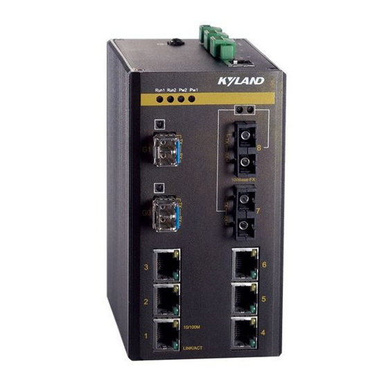
Discard the traditional form of axial fan for heat dissipation, reduce power consumption of the entire unit and increase the stability of the system. The figuration of SICOM3000 case is shown in Figure 3-2. - Page 18 Figure 3-3 SICOM3000’s front panel Gigabit SFP ports SICOM3000 series has 2 Gigabit SFP ports, supporting 2 pairs of redundant 1000Base-LX full duplex SM/MM ports or 2 1000Base-TX RJ45 ports with the port number G1 and G2. The SFP ports adopt SFP modules (LC connector for fiber port, RJ45 connector for TP port). Fiber ports should be used in pairs (TX and RX are a pair).
- Page 19 Meanwhile ports 7 and 8 can be designed to redundant RJ45 copper ports. Ethernet RJ45 ports SICOM3000 series has 6 10/100Base-TX Ethernet RJ45 ports with port numbers 1 to 6. Each of them has self-adaptive function, supporting MDI/MDI-X auto-connection. They can be connected to terminal equipments, severs, hubs or other switches by straight-through or cross-over cables.
-
Page 20: Top Panel (24Vdc, 48Vdc)
No effective network connection in the port 3.2.3 Top panel (24VDC, 48VDC) The top panel of SICOM3000 industrial Ethernet switch has two power input terminals for power redundancy, relay alarm output terminal, grounding protection terminal, etc. Its structure is as figure 3-6. - Page 21 24VDC and 48VDC power input. P1 and P2 can be used singly, or both connect with external DC power supply systems to offer power to SICOM3000, so if one of the two power supply sources fails, the equipment can keep running, which enhance the reliability of network operation.
-
Page 22: Top Panel (110Vdc, 220Vac/Dc)
Figure 3-8 alarm terminal connecting with a alarm lamp 3.2.4 Top panel (110VDC, 220VAC/DC) The top panel of SICOM3000 industrial Ethernet switch has a power input terminal and an relay alarm output terminal, protection grounding terminal, CONSOLE port. Its structure is shown in... - Page 23 SICOM3000 User’s Manual 201001 Power input terminal (7.62mm spacing) When the power supply is 110VDC or 220VAC/DC, use this kind of terminal to connect power cables with multi-strand power cables which section is not less than 0.75 ㎜ . The cable sequence is indicated in Figure 3-10 and the connection and mounting steps are as follows.
- Page 24 Max Switching Power RS232 Network management interface(CONSOLE) The network management interface of SICOM3000 is a shielded RJ45 connector and its interface communication standard is 3-wire RS232. Users can use a network management cable with one end bearing RJ45 plug and the other end DB9F plug to connect the network management interface with the 9-pin serial port in the control computer.
-
Page 25: Chapter 4 Hardware Installation
35mm standard DIN-Rail installation is very convenient for most industrial applications. When you take SICOM3000 out of the packing box, the aluminum connecting seat for Din-Rail has been attached in the rear panel. Before mounting, make sure the following is ready. -
Page 26: Cable Connection
4.4 Optical Fiber Connection SICOM3000 provides 2 pairs of redundant 100Base-FX full duplex SM/MM fiber ports which can form fiber redundant ring network. When the failure occurs in the network, the recovery time is within 50ms. The fiber ports support LC, SC/ST/FC connector. -
Page 27: Cable Wiring
SICOM3000 User’s Manual 201001 The connecting steps are as follows 1. Remove the rubber caps of the fiber ports and keep them for protecting the ports when they are not used. 2. Check whether the ports are clean. Dirty ports might affect the transmitting quality. Use wet handkerchiefs or cotton balls to sweep the cable connectors. - Page 28 SICOM3000 User’s Manual 201001 should meet the design requirements of construction drawings. The laying length of each cable should be determined according to its actual position. 4. No intermediate break or joint is allowed for the cables to be laid.
-
Page 29: Chapter 5: Test Methods
RUN indicators blink. 5.2 TP Port Test As shown in Figure 5-1, after SICOM3000 is powered on, respectively connect two TP ports in the switch to two test computers by straight-through cables, and send the “ping” command to each other. - Page 30 SICOM3000 User’s Manual 201001 As shown in Figure 5-2, firstly two units of SICOM3000 are connected to a fiber chain network. Then connect any RJ45 port in each device with test computers by straight-through cables and send Ping command to each other. They can both get command without packet loss and the corresponding LINK/ACT indicators of the fiber ports go on, showing the testing fiber ports work well.
-
Page 31: Chapter 6: Networking And Configuration
2 pairs of down linked redundant 100Base-FX SM/MM fiber ports or 2 10/100Based-TX RJ45 ports which can form 100M redundant ring network with the recovery time of less than 50ms. SICOM3000 can be widely used in the fields of power, transportation, energy, water treatment, factory automation, etc. - Page 32 Fiber ports can be single mode or multi mode and power supply voltages support 24VDC (18~36VDC), 48VDC(36~48VDC), 110VDC(66~154VDC), 220VAC/DC (132~300VAC/176~400VDC). Detailed configuration and models are shown in Table 6-1 Table 6-1 Configuration table of SICOM3000 Models Description Power supply 2 Gigabit SFP ports, 2×100Base-FX-SM/MM (FC/SC/ST connector), SICOM3000-2GX-2S(M)-6TX 6×10/100Base-TX...
-
Page 33: Appendix A: Twisted-Pair And Pin Distribution
SICOM3000 User’s Manual 201001 Appendix A: Twisted-pair and Pin Distribution For the connection of 10Base-T/100Base-TX, the twisted-pair must have two pair cable. Each pair is distinguished with two different colors. For example, one strand is green, and the other is the alternate of green and white stripes. - Page 34 SICOM3000 User’s Manual 201001 Table A-1 Pin distribution of 10Base-T/100Base-TX MDI-X signal name MDI signal name Receiving data + Output data+(TD+) (RD+) Receiving data - Output data -(TD-) (RD-) Output data +(TD+) Receiving data+ (RD+) Output data-(TD-) Receiving data - (RD-)...
-
Page 35: Appendix B: Cable Type And Specifications
Appendix B Cable Type and Specifications Appendix B: Cable Type and Specifications The cable type and specifications are shown as table B-1: Table B-1 Cable type and specification Cable Type Max. length Connector 10Base-T Cat 3,4 and 5 100ohm UTP 100m RJ-45 100Base-TX... -
Page 36: Appendix C: Glossary
SICOM3000 User’s Manual 201001 Appendix C: Glossary Terminology Explanation Twisted-pair standard of Cat3, Cat4 and Cat5 in IEEE specification for 10Base-T 10Mbps Ethernet Twisted-pair standard of Cat5 or above in IEEE specification for 100Base-TX 100Mbps Fast Ethernet Fast Ethernet which uses one pair of multi-mode or single mode 100Base-FX... - Page 37 SICOM3000 User’s Manual 201001 Use switches to set up the point to point connection among nodes in Full Duplex the LAN and allow them to receive and send data packet at the same time. The communication for two nodes can only move toward one Half Duplex direction at the same time, but cannot move toward both directions.
Need help?
Do you have a question about the SICOM3000 and is the answer not in the manual?
Questions and answers