Table of Contents

Subscribe to Our Youtube Channel
Related Manuals for KYLAND Technology KIEN2204S


Summary of Contents for KYLAND Technology KIEN2204S
- Page 1 KIEN2204S Industrial Ethernet Switch Hardware Installation Manual Kyland Technology Co., Ltd. Publication Date: Mar. 2013 Version: V1.0 FAX: +86-10-88796678 Website: http://www.kyland.com E-mail: support@kyland.com No.: 1.12.02.1046-0...
- Page 2 KIEN2204S Industrial Ethernet Switch Hardware Installation Manual Disclaimer: Kyland Technology Co., Ltd. tries to keep the content of this manual as accurate and as updated as possible. This document is not guaranteed to be error-free, and we reserve the right to amend it without notice to users.
- Page 3 Notice for Safety Operation The product performs reliably as long as it is used according to the guidance. Artificial damage or destruction of the device should be avoided. Before using the device, read this notice carefully for personal and equipment safety. Please keep the manual for further reference. Kyland is not liable to any personal or equipment damage caused by violation of this notice.
- Page 4 Dispose of the device in accordance with relevant national provisions, preventing environmental pollution. In the following cases, please immediately shut down your power supply and contact your Kyland representative: Water gets into the equipment. Equipment damage or shell damage. ...
-
Page 5: Table Of Contents
Contents 1 Product Overview ........................1 2 Structure and Interface ......................2 2.1 Front Panel ........................... 2 2.2 Top Panel ..........................3 3 Mounting ..........................4 3.1 Dimension Drawing ....................... 4 3.2 Mounting Modes and Steps ....................4 3.2.1 DIN-Rail Mounting ......................5 3.2.2 Panel Mounting ....................... -
Page 6: Product Overview
Product Overview 1 Product Overview KIEN2204S includes a series of green low-consumption Power over Ethernet (POE) industrial Ethernet switches applied in the security, highway monitoring, rail transit, railway disaster prevention, coal mining operation, industrial production control, and many other industries. -
Page 7: Structure And Interface
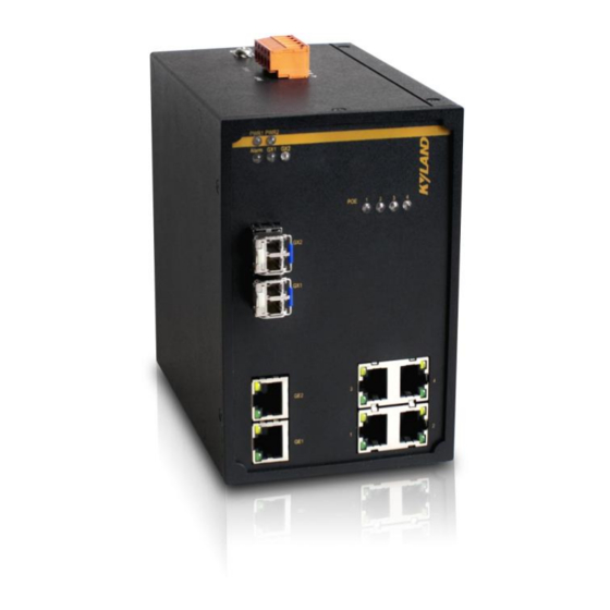
It is recommended to purchase the port dustproof shield (optional) to keep ports clean and ensure switch performance. 2.1 Front Panel Figure 1 Front Panel of KIEN2204S Table 2 Description of the Front Panel of KIEN2204S Identifier Description PWR1 Power 1 LED... -
Page 8: Top Panel
10/100Base-T(X) Ethernet port speed LED (yellow) (13) 10/100Base-T(X) Ethernet port connection status LED (green) (14) POE, 1-4 POE LED 2.2 Top Panel Figure 2 Top Panel of KIEN2204S Table 3 Description of the Top Panel of KIEN2204S Identifier Description Power terminal block Grounding screw... -
Page 9: Mounting
Mounting 3 Mounting 3.1 Dimension Drawing Figure 3 Dimensions for DIN-Rail Mounting (unit: mm) Figure 4 Dimensions for Panel Mounting (unit: mm) Caution: As part of the heat dissipation system, the switch housing becomes hot during operation. Please use caution when coming in contact and avoid covering the switch housing when the switch is running. 3.2 Mounting Modes and Steps The series switches support DIN-rail and panel mounting. -
Page 10: Din-Rail Mounting
Mounting 4) No direct sunlight, distant from heat source and areas with strong electromagnetic interference. 3.2.1 DIN-Rail Mounting Mounting Step 1: Select the mounting position for the device and guarantee adequate space and heat dissipation (dimensions: 88mm×135mm×137mm). Step 2: Insert the connecting seat onto the top of the DIN rail, and push the bottom of the device inward and upward to ensure the DIN rail fits in the connecting seat. -
Page 11: Panel Mounting
Mounting 3.2.2 Panel Mounting Caution: Purchase the plate (optional) for panel mounting. Panel Mounting Step 1: Use screws to secure the plate for panel mounting to the rear panel of the device. Step 2: Select the mounting position (on a wall or inner wall of a cabinet) for the device and guarantee adequate space and heat dissipation (dimensions: 88mm×135mm×137mm). - Page 12 Mounting Panel Dismounting Step 1: Loosen the four screws with a screwdriver. Pull the device upward until the four screws are in the Ф6.5 positions in the following figure. Then remove the plate for panel mounting from the four screws to detach the device from the wall or inner wall of the cabinet. Step 2: Loosen the screws completely with a screwdriver.
-
Page 13: Connection
POE The 10/100Base-T(X) Ethernet ports of KIEN2204S support 802.3at POE output. Serving as the Power Sourcing Equipment (PSE), KIEN2204S can provide power supply for PDs through 10/100Base-T(X) Ethernet ports. Each POE port provides 30W feed (44-57VDC). - Page 14 Connection The following table lists the pin definitions of the 10/100Base-T(X) RJ45 port. Table 4 Pin Definitions of 10/100Base-T(X) RJ45 Port MDI-X Signal MDI Signal Receive Data+ (RD+) Transmit Data+ (TD+) Receive Data- (RD-) Transmit Data- (TD-) Transmit Data+ (TD+) Receive Data+ (RD+) Transmit Data- (TD-) Receive Data- (RD-)
-
Page 15: 10/100/1000Base-T(X) Ethernet Port
Connection 4.2 10/100/1000Base-T(X) Ethernet Port 10/100/1000Base-T(X) Ethernet port is equipped with RJ45 connector. The port is self-adaptive. It can automatically configure itself to work in 10M, 100M, or 1000M state, full or half duplex mode. The port can also adapt to MDI or MDI-X connection automatically. You can connect the port to a terminal or network device with a straight-through or cross-over cable. -
Page 16: 1000Base-X, 10/100/1000Base-T(X) Sfp Slot
4.3 1000Base-X, 10/100/1000Base-T(X) SFP Slot 1000Base-X, 10/100/1000Base-T(X) SFP slot (gigabit SFP slot) requires an SFP optical/electrical module to enable data transmission. The following table lists the gigabit SFP optical/electrical modules (optional) supported by KIEN2204S. Table 6 Gigabit SFP Optical/Electrical Modules Central... -
Page 17: Gigabit Sfp Optical Module
Connection 4.3.1 Gigabit SFP Optical Module Figure 13 Gigabit SFP Optical Module An SFP optical module is equipped with LC connector, and each port consists of a TX (transmit) port and an RX (receive) port. To enable communication between Device A and Device B, connect the TX port of Device A to the RX port of Device B, and the RX port of Device A to the TX port of Device B, as shown in the following figure. -
Page 18: Gigabit Sfp Electrical Module
Connection Caution: The device uses laser to transmit signals in fibers. The laser meets the requirements of level 1 laser products. Routine operation is not harmful to your eyes, but do not look directly at the fiber port when the device is powered on. -
Page 19: Grounding
Connection The following table lists the gigabit SFP slots and 10/100/1000Base-T(X) Ethernet ports of the Combo ports. Table 7 Combo Port Combo Port Gigabit SFP Slot 10/100/1000Base-T(X) Ethernet Port 4.5 Grounding Grounding protects the switch from lightning and interference. Therefore, you must ground the switch properly. -
Page 20: Power Terminal Block
Connection 4.6 Power Terminal Block There is a power terminal block on the top panel of the device. You need to connect the power wires to the terminal block to provide power for the device. The device supports redundant power supply with 5-pin 5.08mm-spacing plug-in terminal block. - Page 21 Connection device. Step 5: Connect the other end of the power wires to the external power supply system according to the power supply requirements of the device. View the status of the power LEDs on the front panel. If the LEDs are on, the power is connected properly. Figure 20 Connection of 5-Pin 5.08mm-Spacing Plug-in Terminal Block Caution: The switch supports 48DC power input.
-
Page 22: Leds
LEDs 5 LEDs Table 9 Front Panel LEDs State Description Power 1 is connected and operates properly. Power 1 LED Power 1 is not connected or operates abnormally. Power 2 is connected and operates properly. Power 2 LED Power 2 is not connected or operates abnormally. Effective port connection Gigabit SFP slot connection status Blinking Ongoing network activities... -
Page 23: Basic Features And Specifications
Basic Features and Specifications 6 Basic Features and Specifications Power Requirements Power Identifier Rated Voltage Range Maximum Voltage Range 48DC 48VDC 44-57VDC Terminal block 5-pin 5.08mm-spacing plug-in terminal block Rated Power Consumption Rated power consumption (no PD) 6W (MAX) Physical Characteristics Housing Aluminum, fanless Installation...
Need help?
Do you have a question about the KIEN2204S and is the answer not in the manual?
Questions and answers