
Subscribe to Our Youtube Channel
Related Manuals for KYLAND Technology SICOM3016BA-4GX-12S/M


Summary of Contents for KYLAND Technology SICOM3016BA-4GX-12S/M
- Page 1 SICOM3016BA Industrial Ethernet Switch Hardware Installation Manual Kyland Technology Co., Ltd. Publication Date: Apr. 2013 Version: V1.1 FAX: +86-10-88796678 Website: http://www.kyland.com E-mail: support@kyland.com...
- Page 2 SICOM3016BA Industrial Ethernet Switch Hardware Installation Manual Disclaimer: Kyland Technology Co., Ltd. tries to keep the content of this manual as accurate and as updated as possible. This document is not guaranteed to be error-free, and we reserve the right to amend it without notice to users.
- Page 3 Notice for Safety Operation This product performs reliably as long as it is used according to the guidance. Artificial damage or destruction of the equipment should be avoided. Read this manual carefully and keep it for future reference; Do not place the equipment near water sources or damp areas; ...
-
Page 4: Table Of Contents
Contents 1 Product Overview ..................1 2 Structure and Interface ................1 2.1 Front Panel ....................1 2.2 Top Panel ....................2 3 Mounting ...................... 3 3.1 Dimension Drawing ................. 3 3.2 Mounting Modes and Steps ..............4 4 Cable Connection ..................6 4.1 10/100Base-T(X) Port ................ -
Page 5: Product Overview
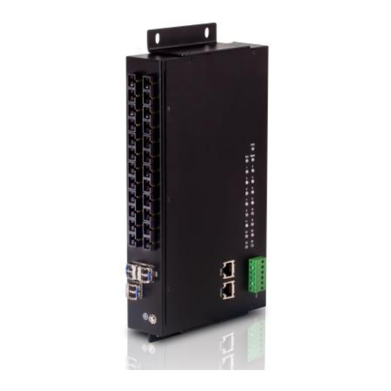
1 Product Overview SICOM3016BA is an intrinsically safe gigabit industrial Ethernet switch developed by Kyland. The switch is equipped with high-performance switching engine, overcurrent-, overvoltage-, and EMC-protection power supply, outstanding EMC protection on RJ45 ports, and redundant power input. All these features guarantee the reliably operation of the system. SICOM3016BA provides powerful network management functions. -
Page 6: Top Panel
Table 1 Front Panel of SICOM3016BA-4GX-6S/M-6T Identifier Description 100Base-FX port 7-12 10/100Base-T(X) port 10/100Base-T(X) RJ45 port speed LED 10/100Base-T(X) RJ45 port Link/ACT LED GX1-GX4 1000Base-X SFP port Grounding screw Mounting ear 2.2 Top Panel 1 2 3 Figure 2 Top Panel Table 2 Top Panel of SICOM3016BA Identifier Description... -
Page 7: Mounting
1-12 Fast Ethernet port LED G1-G4 1000Base-X SFP port LED + - + - ACAlarm - Power terminal block Console Console port Debug Debug port Mounting ear 3 Mounting 3.1 Dimension Drawing SICOM3016BA Integrated Device (unit: mm) 12.5 Figure 3 SICOM3016BA (Integrated Device) -
Page 8: Mounting Modes And Steps
SICOM3016BA Bare Board (unit: mm) Figure 4 SICOM3016BA (Bare Board) 3.2 Mounting Modes and Steps As mentioned in the first chapter, SICOM3016BA has two forms, that is, integrated device and bare board. A bare board can be directly installed in the target device, while the integrated device supports panel mounting. - Page 9 the largest radius) of the four holes on the mounting ears of SICOM3016BA. Move SICOM3016BA to the right (or left) until the screws are located at the left (or right) ends (the part with the smallest radius) of the mounting holes. Tighten the screws. In this way, you can secure the device to the wall or inner wall of a cabinet, as shown in Figure 5.
-
Page 10: Cable Connection
Figure 6 Panel Dismounting 4 Cable Connection 4.1 10/100Base-T(X) Port 10/100Base-T(X) port is equipped with RJ45 connector. The port is self-adaptive. It can automatically configure itself to work in 10M or 100M state, full or half duplex mode. The port can also adapt to MDI or MDI-X connection automatically. - Page 11 Table 3 Pin Definition of 10/100Base-T(X) RJ45 Port MDI-X Signal MDI Signal Receive Data+ (RD+) Transmit Data+ (TD+) Receive Data- (RD-) Transmit Data- (TD-) Transmit Data+ (TD+) Receive Data+ (RD+) Transmit Data- (TD-) Receive Data- (RD-) 4, 5, 7, 8 Unused Unused Note: "+"...
-
Page 12: 100Base-Fx Port
4.2 100Base-FX Port 100Base-FX port is equipped with FC/ST/SC connector, and each port consists of TX (transmit) port and RX (receive) port, as shown in Figure 10. Figure 10 shows 100Base-FX port wiring. (The following uses the SC port as example; ST/FC wiring method is the same with SC.) To enable data transmission between Switch A and Switch B, connect the TX (transmit) port of Switch A to the RX (receive) port of Switch B, and the RX (receive) port of Switch A to the TX (transmit) port of Switch B. - Page 13 Gigabit SFP module is equipped with LC connector, and each port consists of a TX (transmit) port and an RX (receive) port, as shown in Figure 12. To enable data transmission between Switch A and Switch B, connect the TX (transmit) port of Switch A to the RX (receive) port of Switch B, and the RX (receive) port of Switch A to the TX (transmit) port of Switch B, as shown in Figure 12.
-
Page 14: Console Port
Figure 13 Connecting the Gigabit SFP Optical Module Caution: The device uses laser to transmit signals in fibers. The laser meets the requirements of level 1 laser products. Routine operation is not harmful to your eyes, but do not look directly at the fiber port when the device is powered on. -
Page 15: Debug Port
9-pin serial port of a PC. Figure 15 shows the pin numbers of the DB9 connector. Figure 15 DB9 Connector Table 4 lists the pin definitions of the DB9 connector. Table 4 Pin Definition of DB9 Connector Definition Receive Data (RXD) Transmit Data (TXD) 1, 4, 6, 7, 8, 9 Unused... - Page 16 details, see sections 6.2 and 6.3. Figure 17 Debug Port Figure 18 Cable Connection of Debug Port The debug port is self-adaptive. It can automatically configure itself to work in 10M or 100M state, full or half duplex mode. The port can also adapt to MDI or MDI-X connection automatically.
-
Page 17: Power Terminal Block
Transmit Data- (TD-) Receive Data- (RD-) 4, 5, 7, 8 Unused Unused Note: "+" and "-" indicate level polarities. Wiring Sequence Figure 20 Connection Using Straight-through Cable Figure 21 Connection Using Cross-over Cable Note: The color of the cable for RJ45 connector meets the 568B standard: 1-orange and white, 2-orange, 3-green and white, 4-blue, 5-blue and white, 6-green, 7-brown and white, and 8-brown. - Page 18 6-Pin 5.08mm-Spacing Plug-in Terminal Block Figure 22 shows the pin numbers of the 6-pin 5.08mm-spacing plug-in terminal block. 1 2 3 4 5 Figure 22 6-Pin 5.08mm-Spacing Plug-in Terminal Block (socket) Table 6 lists the pin definitions of the 6-pin 5.08mm-spacing plug-in terminal block.
-
Page 19: Grounding
4.7 Grounding Figure 23 GND There is a grounding screw on the front panel of SICOM3016BA. The screw is for chassis grounding. Connect one end of the grounding cable to the grounding screw and the other end to the earth firmly (cross-sectional area of the chassis grounding cable>2.5mm ;... -
Page 20: Switch Access
No effective port connection 10/100Base-T(X) RJ45 Port LED Each RJ45 port has two LEDs. The yellow one indicates port rate while the green one indicates port connection state. 100M working state Speed (yellow) 10M working state or no connection Effective port connection Blinking Ongoing network activities Link/ACT (green) - Page 21 Figure 24 Creating a Connection Step 4: Select the COM port in use (You can view the port in use in Device Manager), as shown in Figure 25. Figure 25 Selecting a Serial Port Step 5: Set port parameters (Bits per second: 9600, Data bits: 8, Parity: None, Stop bits: 1, and Flow control: None), as shown in Figure...
-
Page 22: Access Through Telnet
Figure 26 Setting Port Parameters Step 6: Click OK to enter the switch CLI. Then you can run the following commands to perform operations. Table 8 CLI Commands View Command Description User view SWITCH>enable Enter the management view. Management view SWITCH#show interface Query the IP address of the switch. -
Page 23: Access Through Web
7 Product Configuration Information Table 9 and Table 10 list the models supported by SICOM3016BA. Table 9 SICOM3016BA Configuration (Integrated Device) Model Interface Power Four 1000Base-X SFP ports, twelve SICOM3016BA-4GX-12S/M 100Base-FX ports, SM (MM), FC/ST/SC connector 5DC, 12DC Four 1000Base-X ports,... - Page 24 Four 1000Base-X ports, 100Base-FX ports, SM (MM), FC/ST/SC SICOM3016BA-4GX-6S/M-6T connector, six 10/100Base-T(X) adaptive RJ45 ports Four 1000Base-X ports, SICOM3016BA-4GX-6S/M 100Base-FX ports, SM (MM), FC/ST/SC connector Note: SICOM3016BA (integrated device) also provides 3GX and 2GX models as well as models without gigabit ports. The identifiers (for example, 6S/M) for 100M ports in the names of the other models are identical with those of models listed in Table 9.
-
Page 25: Basic Features And Specifications
-6S/M 1000Base-X SFP ports, six 100Base-FX ports, SM (MM), FC/ST/SC connector Note: SICOM3016BA (bare board) also provides 3GX and 2GX models as well as models without gigabit ports. The identifiers (for example, 6S/M) for 100M ports in the names of the other models are identical with those of models listed in Table 10. - Page 26 Power consumption <10.6W Physical Characteristics Housing: Metal, fanless Installation: Panel (integrated device) or plug-in (bare board) mounting Dimensions (W×H×D): 284mm×44mm×140mm (integrated device) 235mm×130mm (bare board, W×D) Weight: 1.5kg Environmental Limits Operating temperature: -40℃ to +85℃ Storage temperature: -40℃ to +85℃ Ambient relative humidity: 5% to 95% (non-condensing) ...
Need help?
Do you have a question about the SICOM3016BA-4GX-12S/M and is the answer not in the manual?
Questions and answers