
Related Manuals for KYLAND Technology SICOM2024M-4S/M-24T


Summary of Contents for KYLAND Technology SICOM2024M-4S/M-24T
- Page 1 SICOM2024M Industrial Ethernet Switch Hardware Installation Manual Kyland Technology Co., Ltd. Publication Date: Sep. 2013 Version: V4.3 FAX: +86-10-88796678 Website: http://www.kyland.com E-mail: support@kyland.com...
- Page 2 SICOM2024M Industrial Ethernet Switch Hardware Installation Manual Disclaimer: Kyland Technology Co., Ltd. tries to keep the content of this manual as accurate and as updated as possible. This document is not guaranteed to be error-free, and we reserve the right to amend it without notice to users.
- Page 3 Notice for Safety Operation The product performs reliably as long as it is used according to the guidance. Artificial damage or destruction of the device should be avoided. Before using the device, read this notice carefully for personal and equipment safety. Please keep the manual for further reference. Kyland is not liable to any personal or equipment damage caused by violation of this notice.
- Page 4 Do not purchase parts from other channels. Dispose of the device in accordance with relevant national provisions, preventing environmental pollution. In the following cases, please immediately shut down your power supply and contact your Kyland representative: Water gets into the equipment. ...
-
Page 5: Table Of Contents
Contents 1 Product Overview ........................1 2 Structure and Interface ......................2 2.1 Front Panel ............................2 2.2 Rear Panel ............................3 3 Mounting ..........................8 3.1 Dimension Drawing .......................... 8 3.2 Mounting Modes and Steps ......................8 4 Connection ..........................11 4.1 10/100Base-T(X) Ethernet Port ...................... -
Page 6: Product Overview
Table 1 SICOM2024M Models Port Model 100Base-FX 10/100Base-T(X) Power Supply Ethernet port Ethernet port SICOM2024M-4S/M-24T SICOM2024M-2S/M-24T 220AC/DCW, 220AC/DC, 48DC, 24DC SICOM2024M-1S/M-24T (single and redundant power supply) SICOM2024M-24T SICOM2024M-16T Note: We reserve the right to amend the product information listed in this table without notice. To obtain the... -
Page 7: Structure And Interface
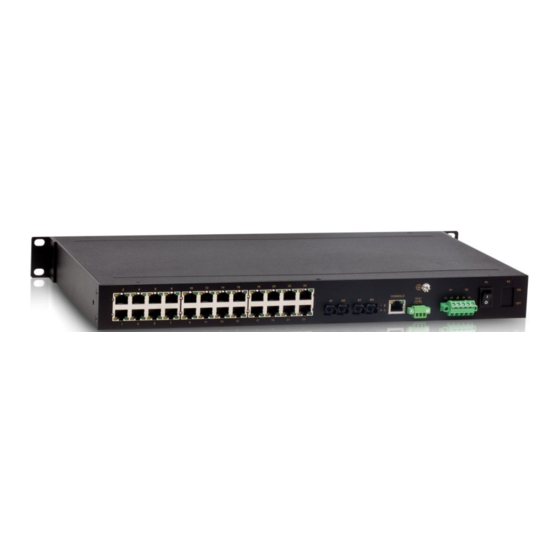
To keep ports clean and ensure switch performance, you are advised to purchase the port dustproof shield (optional). 2.1 Front Panel Front Panel (1) Applicable to: SICOM2024M-4S/M-24T SICOM2024M-2S/M-24T SICOM2024M-24T Figure 1 Front Panel (1) Table 2 Description of Front Panel (1) -
Page 8: Rear Panel
Connection status LEDs for twenty-four 10/100Base-T(X) Ethernet ports 1-24: Speed Speed LEDs for twenty-four 10/100Base-T(X) Ethernet ports 2.2 Rear Panel Rear Panel of SICOM2024M-4S/M-24T Figure 3 Rear Panel of SICOM2024M-4S/M-24T Table 4 Description of Rear Panel of SICOM2024M-4S/M-24T Identifier Description... - Page 9 Structure and Interface 1-24 Twenty-four 10/100Base-T(X) Ethernet ports 10/100Base-T(X) Ethernet port speed LED 10/100Base-T(X) Ethernet port connection status LED FAULT Alarm terminal block LINK/ACT 100Base-FX Ethernet port connection status LED 100Base-FX Ethernet port (Its status is indicated by G1 on the front panel.) 100Base-FX Ethernet port (Its status is indicated by G2 on the front panel.)
- Page 10 Structure and Interface 10/100Base-T(X) Ethernet port speed LED 10/100Base-T(X) Ethernet port connection status LED FAULT Alarm terminal block Link/ACT 100Base-FX Ethernet port connection status LED 100Base-FX Ethernet port (Its status is indicated by G1 on the front panel.) 100Base-FX Ethernet port (Its status is indicated by G3 on the front panel.) Grounding screw Power terminal block (10) PWR1&PWR2: ON/OFF...
- Page 11 Structure and Interface (10) P1&P2: ON/OFF Switches for Power 1 and Power 2 Rear Panel of SICOM2024M-24T (The model involves two types of rear panels. You can refer to the following descriptions according to your panel type.) Figure 6 Rear Panel (1) of SICOM2024M-24T Table 7 Description of Rear Panel (1) of SICOM2024M-24T Identifier Description...
- Page 12 Structure and Interface Identifier Description 1-24 Twenty-four 10/100Base-T(X) Ethernet ports 10/100Base-T(X) Ethernet port speed LED 10/100Base-T(X) Ethernet port connection status LED Console Console port Alarm terminal block Grounding screw Power terminal block P1&P2: ON/OFF Switches for Power 1 and Power 2 ...
-
Page 13: Mounting
Mounting P1&P2: ON/OFF Switches for Power 1 and Power 2 3 Mounting 3.1 Dimension Drawing Figure 9 Dimension Drawing (unit: mm) Caution: As part of the heat dissipation system, the switch housing becomes hot during operation. Please use caution when coming in contact and avoid covering the switch housing when the switch is running. ... - Page 14 Mounting similar to those for mounting by front panel. Before installation, make sure that the following requirements are met. 1) Environment: temperature (-40℃ to 85℃), ambient relative humidity (5% to 95%, non-condensing) 2) Power requirement: The power input is within the voltage range of the switch. 3) Grounding resistance: <5...
- Page 15 Mounting dissipation for it (dimensions: 440mm×44mm×245mm). Step 2: Move the switch in direction 1 until the screw holes for securing the mounting brackets to rack posts are in alignment with the corresponding holes in the rack posts. Then use four screws and supporting captive nuts to secure the mounting brackets to the rack posts.
-
Page 16: Connection
Connection 4 Connection 4.1 10/100Base-T(X) Ethernet Port 10/100Base-T(X) Ethernet port is equipped with RJ45 connector. The port is self-adaptive. It can automatically configure itself to work in 10M or 100M state, full or half duplex mode. The port can also adapt to MDI or MDI-X connection automatically. You can connect the port to a terminal or network device with a straight-through or cross-over cable. -
Page 17: 100Base-Fx Ethernet Port
Connection Figure 14 Connection Using Straight-through/Cross-over Cable Note: The color of the cable for RJ45 connector meets the 568B standard: 1-orange and white, 2-orange, 3-green and white, 4-blue, 5-blue and white, 6-green, 7-brown and white, and 8-brown. 4.2 100Base-FX Ethernet Port 100Base-FX Ethernet port is equipped with FC/ST/SC connector, and each port consists of TX (transmit) port and RX (receive) port. -
Page 18: Console Port
Connection device is powered on. 4.3 Console Port Connect the 9-pin serial port of a PC to the console port of the switch with an RJ45-DB9 console cable. Then you can configure, maintain, and manage the switch by running the Hyper Terminal in the Windows OS of the computer. -
Page 19: Power Terminal Block
Connection switch properly. You need to ground the switch before it is powered on and disconnect the grounding cable after the switch is powered off. The switch provides a grounding screw on the rear panel for chassis grounding. After crimping one end of the grounding cable to a cold pressed terminal, secure the end to the grounding screw and connect the other end to the earth firmly. - Page 20 Connection The following table lists the pin definitions of the 5-pin 5.08mm-spacing plug-in terminal block. Table 12 Pin Definitions of 5-Pin 5.08mm-Spacing Plug-in Terminal Block DC Definition AC Definition Power 1: + Power 1: L Power 1: - Power 1: N PGND PGND Power 2: -...
-
Page 21: Alarm Terminal Block
Connection Figure 20 Connection of 5-Pin 5.08mm-Spacing Plug-in Terminal Block Caution: The switch supports 220AC/DCW, 220AC/DC, 48DC, and 24DC power input. Before connecting the device to power supply, make sure that the power input meets the power requirement. If connected to an incorrect power input, the device may be damaged. - Page 22 Connection Figure 21 Alarm Terminal Block (socket) Electrical parameters of the relay: Max Switch Voltage: 250VAC/220VDC; Max Switch Current: 2A Max Switching Power: 60W Dielectric Strength: 2KV Note: Pin 1 and pin 2 are normally-open contacts; pin 2 and pin 3 are normally-closed contacts. When the switch works properly, pin 1 and pin 2 are closed, pin 2 and pin 3 are open;...
-
Page 23: Leds
LEDs 5 LEDs Table 13 Front Panel LEDs State Description Power 1 is connected and operates properly. Power 1 LED Power 1 is not connected or operates abnormally. Power 2 is connected and operates properly. Power 2 LED Power 2 is not connected or operates abnormally. Blinking The CPU operates properly. - Page 24 LEDs 10/100Base-T(X) Ethernet port 100M working state (100Base-TX) speed LED (yellow) 10M working state (10Base-T) or no connection Effective port connection 10/100Base-T(X) Ethernet port Blinking Ongoing network activities connection status LED (green) No effective port connection Effective port connection 100Base-FX Ethernet port Blinking...
-
Page 25: Switch Access
Switch Access Switch Access You can access the switch in any of the following ways: 6.1 Access through Console Port Step 1: Connect the console port of the switch to the 9-pin serial port of a PC with the delivered RJ45-DB9 console cable. - Page 26 Switch Access Figure 23 Selecting a Serial Port Note: To confirm the communication port in use, right-click [My Computer] and select [Property]. Click [Hardware] → [Device Manager] → [Port] to view the communication port. Step 5: Set port parameters (Bits per second: 9600, Data bits: 8, Parity: None, Stop bits: 1, and Flow control: None), as shown in the following figure.
-
Page 27: Access Through Telnet
Switch Access Figure 24 Setting Port Parameters Step 6: Click OK to enter the switch CLI. Then you can run the following commands to perform operations. Table 15 CLI Commands View Command Description User view SWITCH>enable Enter the management view. Management view SWITCH#show interface Query the current IP address of the switch. - Page 28 Switch Access interface is displayed. You can log in to the Web UI by default user name "admin" and password "123". Note: IE8.0 or a later version is recommended. For details about how to access the switch and other operations, refer to the Web operation manual in the delivered CD.
-
Page 29: Basic Features And Specifications
Basic Features and Specifications 7 Basic Features and Specifications Power Requirements Power Identifier Rated Voltage Range Maximum Voltage Range 24DC 24VDC 18-36VDC 48DC 48VDC 36-72VDC 220AC/DC 100-240VAC, 50/60Hz; 220VDC 85-264VAC/120-300VDC 220AC/DCW 100-240VAC, 50/60Hz; 110-220VDC 85-264VAC/77-300VDC Terminal block 5-pin 5.08mm-spacing plug-in terminal block Rated Power Consumption Rated power consumption <16.8W...
Need help?
Do you have a question about the SICOM2024M-4S/M-24T and is the answer not in the manual?
Questions and answers