Table of Contents
Advertisement
Quick Links
Advertisement
Table of Contents

Subscribe to Our Youtube Channel
Related Manuals for KYLAND Technology SICOM3024PT-18MB


Summary of Contents for KYLAND Technology SICOM3024PT-18MB
- Page 1 SICOM3024PT Industrial Ethernet Switch Hardware Installation Manual Kyland Technology Co., Ltd. Publication Date: Jan, 2013 Version: V2.3 Customer Service Hotline: (+8610) 88796676 FAX: (+8610) 88796678 Website: http://www.kyland.cn E-mail: support@kyland.biz...
- Page 2 SICOM3024PT Industrial Ethernet Switch Hardware Installation Manual Disclaimer: Kyland Technology Co., Ltd. tries to keep the content of this manual as accurate and as updated as possible. This document is not guaranteed to be error-free, and we reserve the right to amend it without notice to users.
- Page 3 Notice for Safety Operation The product performs reliably as long as it is used according to the guidance. Artificial damage or destruction of the device should be avoided. Before using the device, read this notice carefully for personal and equipment safety. Please keep the manual for further reference. Kyland is not liable to any personal or equipment damage caused by violation of this notice.
- Page 4 If any part is lost, contact our sales or technical support personnel to purchase the substitute. Do not purchase parts from other channels. Dispose of the device in accordance with relevant national provisions, preventing environmental pollution. In the following cases, please immediately shut down your power supply and contact your Kyland representative: ...
-
Page 5: Table Of Contents
Contents 1 Product Overview ........................1 2 Structure and Interface ......................3 2.1 Front Panel ......................... 3 2.2 Rear Panel .......................... 6 2.2.1 Interface Modules ......................6 2.2.2 Rear Panel ........................7 3 Mounting ..........................9 3.1 Dimension Drawing ......................9 3.2 Mounting Modes and Steps .................... - Page 6 7 Basic Features and Specifications ..................30...
-
Page 7: Product Overview
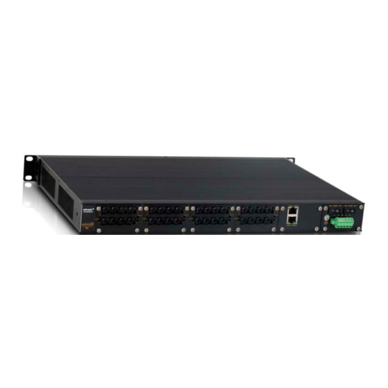
SICOM3024PT-18MB and SICOM3024PT-28MB. Both of them conform to IEEE1588-2008, IEC61850-3, and IEEE1613. SICOM3024PT-18MB supports 19 inch 1U rack mounting and provides five slots for 100M interface modules. SICOM3024PT-28MB supports 19 inch 2U rack mounting and provides one slot for gigabit interface module and six slots for 100M interface modules. - Page 8 Product Overview SM3.1-2S/M-2T Applicable to slot 1 to slot 4 of SICOM3024PT-18MB and slot 1 to SM3.1-4T slot 6 of SICOM3024PT-28MB SM3.1-2T 1U interface module Only applicable to slot 5 of SICOM3024PT-18MB Caution: We will provide you with the integrated device according to your requirements on the number and type of ports.
-
Page 9: Structure And Interface
To keep ports clean and ensure switch performance, you are advised to purchase the port dustproof shield (optional). 2.1 Front Panel Front Panel of SICOM3024PT-18MB Figure 1 Front Panel of SICOM3024PT-18MB Table 3 Description of Front Panel of SICOM3024PT-18MB Identifier Description ALARM Alarm LED... - Page 10 Structure and Interface 100M port connection status LEDs, indicating the connection statuses of port 1 to (6/1) 1-4 (LINK/ACT) port 4 on the interface module in slot 1 100M port connection status LEDs, indicating the connection statuses of port 1 to (6/2) 5-8 (LINK/ACT) port 4 on the interface module in slot 2 9-12...
- Page 11 Structure and Interface Gigabit port connection status LEDs, indicating the connection statuses of port 1 to G1-G4 (LINK) port 4 on the interface module in slot 7 100M port speed LEDs, indicating the speeds of port 1 to port 4 on the interface (7/1) 1-4 (10M/100M) module in slot 1 100M port speed LEDs, indicating the speeds of port 1 to port 4 on the interface...
-
Page 12: Rear Panel
Structure and Interface 2.2 Rear Panel 2.2.1 Interface Modules 100M Interface Modules Figure 3 100M Interface Modules Table 5 Description of 100M Interface Modules Identifier Description (1)-(4) Port 1 to port 4 Speed 10/100Base-T(X) Ethernet port speed LED 10/100Base-T(X) Ethernet port Link/ACT 10/100Base-T(X) Ethernet port connection status LED 100Base-FX Ethernet port... -
Page 13: Rear Panel
Link/ACT 10/100/1000Base-T(X) Ethernet port connection status LED 2.2.2 Rear Panel Rear Panel of SICOM3024PT-18MB Figure 5 Rear Panel of SICOM3024PT-18MB Table 7 Description of Rear Panel of SICOM3024PT-18MB Identifier Description Interface module slot 1 Interface module slot 2 Interface module slot 3 Interface module slot 4 Interface module slot 5 (for SM3.1-2T only) - Page 14 Structure and Interface Figure 6 Rear Panel of SICOM3024PT-28MB Table 8 Description of Rear Panel of SICOM3024PT-28MB Identifier Description Interface module slot 1 Interface module slot 2 Interface module slot 3 Interface module slot 4 Interface module slot 5 Interface module slot 6 Interface module slot 7 (for SM3.1-4GX or SM3.1-4GE only) Grounding screw Switch for Power 1...
-
Page 15: Mounting
Mounting 3 Mounting 3.1 Dimension Drawing Figure 7 Dimension Drawing for SICOM3024PT-18MB (unit: mm) -
Page 16: Mounting Modes And Steps
Mounting Figure 8 Dimension Drawing for SICOM3024PT-28MB (unit: mm) Caution: As part of the heat dissipation system, the switch housing becomes hot during operation. Please use caution when coming in contact and avoid covering the switch housing when the switch is running. -
Page 17: Installing Mounting Brackets
As shown in the following figure, use three screws to secure two mounting brackets to the switch respectively. Figure 10 Installing Mounting Brackets for SICOM3024PT-18MB SICOM3024PT-28MB... -
Page 18: Mounting
Mounting Figure 11 Mounting Bracket for SICOM3024PT-28MB You can select the screw holes for front or rear panel mounting to install the mounting brackets. If there are screws inserted in the screw holes, remove the screws and keep them for future use. As shown in the following figure, use six screws to secure two mounting brackets to the switch respectively. - Page 19 Mounting Figure 13 Mounting Dismounting Step 1: Remove the four screws and supporting captive nuts securing the mounting brackets to the rack posts. Step 2: Remove the switch from the rack posts. Then unscrew the mounting brackets to complete dismounting.
-
Page 20: Connection
Connection 4 Connection 4.1 10/100Base-T(X) Ethernet Port 10/100Base-T(X) Ethernet port is equipped with RJ45 connector. The port is self-adaptive. It can automatically configure itself to work in 10M or 100M state, full or half duplex mode. The port can also adapt to MDI or MDI-X connection automatically. You can connect the port to a terminal or network device with a straight-through or cross-over cable. -
Page 21: 100Base-Fx Ethernet Port
Connection Figure 15 Connection Using Straight-through/Cross-over Cable Note: The color of the cable for RJ45 connector meets the 568B standard: 1-orange and white, 2-orange, 3-green and white, 4-blue, 5-blue and white, 6-green, 7-brown and white, and 8-brown. 4.2 100Base-FX Ethernet Port 100Base-FX Ethernet port is equipped with FC/ST/SC connector, and each port consists of TX (transmit) port and RX (receive) port. -
Page 22: 10/100/1000Base-T(X) Ethernet Port
Connection the device is powered on. 4.3 10/100/1000Base-T(X) Ethernet Port 10/100/1000Base-T(X) Ethernet port is equipped with RJ45 connector. The port is self-adaptive. It can automatically configure itself to work in 10M, 100M, or 1000M state, full or half duplex mode. The port can also adapt to MDI or MDI-X connection automatically. You can connect the port to a terminal or network device with a straight-through or cross-over cable. -
Page 23: 1000Base-X Sfp Slot
Connection Figure 18 Connection Using Straight-through/Cross-over Cable Note: The color of the cable for RJ45 connector meets the 568B standard: 1-orange and white, 2-orange, 3-green and white, 4-blue, 5-blue and white, 6-green, 7-brown and white, and 8-brown. 4.4 1000Base-X SFP Slot You can enable data transmission only after inserting an SFP optical module into the 1000Base-X SFP slot and connecting fibers properly. -
Page 24: Gigabit Sfp Optical Module
Connection 4.4.1 Gigabit SFP Optical Module Figure 19 Gigabit SFP Optical Module Gigabit SFP optical module is equipped with LC connector, and each port consists of a TX port and an RX port. To enable communication between Device A and Device B, connect the TX port of Device A to the RX port of Device B, and the RX port of Device A to the TX port of Device B, as shown in the following figure. -
Page 25: Console Port
Connection connectors at one end of the fibers. Caution: The device uses laser to transmit signals in fibers. The laser meets the requirements of level 1 laser products. Routine operation is not harmful to your eyes, but do not look directly at the fiber port when the device is powered on. -
Page 26: Grounding
Connection Figure 23 Wiring Sequence of DB9-RJ45 Console Cable Table 12 Pin Definitions of DB9-RJ45 Console Cable DB9 Pin RJ45 Pin Signal Description Receive data Transmit data Grounding 4.6 Grounding Grounding protects the switch from lightning and interference. Therefore, you must ground the switch properly. - Page 27 Connection redundant power supply with 5-pin 5.08mm-spacing plug-in terminal block. When the redundant power supply is used and one power input is faulty, the device can continue operating properly, thereby improving network reliability. Note: 0.75mm <Cross-sectional area of the power wire<2.5mm ;...
-
Page 28: Alarm Terminal Block
Connection wires. Step 4: Insert the terminal block with the connected wires into the terminal block socket on the device. Step 5: Connect the other end of the power wires to the external power supply system according to the power supply requirements of the device. Turn on the switch for the connected power (power 1, power 2, or both). - Page 29 Connection contacts are open; when an alarm occurs, the normally-open contacts are open and the normally-closed contacts are closed. The alarm is outputted through a 3-pin 3.81mm-spacing plug-in terminal block. Figure 27 Alarm Terminal Block (socket) Electrical parameters of the relay: Max Switch Voltage: 250VAC/220VDC;...
-
Page 30: Leds
LEDs 5 LEDs The following table lists the descriptions of front panel LEDs. Table 14 Front Panel LEDs State Description Power 1 is connected and operates properly. Power 1 LED Power 1 is not connected or operates abnormally. Power 2 is connected and operates properly. Power 2 LED Power 2 is not connected or operates abnormally. - Page 31 LEDs Table 15 LEDs for Interface Modules State Description 10/100Base-T(X) Ethernet port 100M working state (100Base-TX) speed LED (yellow) 10M working state (10Base-T) or no connection Effective port connection 10/100Base-T(X) Ethernet port Blinking Ongoing network activities connection status LED (green) No effective port connection 1000M working state (1000Base-TX) 10/100/1000Base-T(X)
-
Page 32: Switch Access
Switch Access 6 Switch Access You can access the switch in any of the following ways: 6.1 Access through Console Port Step 1: Connect the console port of the switch to the 9-pin serial port of a PC with the delivered RJ45-DB9 console cable. - Page 33 Switch Access Figure 29 Selecting a Serial Port Note: To confirm the communication port in use, right-click [My Computer] and select [Property]. Click [Hardware] → [Device Manager] → [Port] to view the communication port. Step 5: Set port parameters (Bits per second: 9600, Data bits: 8, Parity: None, Stop bits: 1, and Flow control: None), as shown in the following figure.
-
Page 34: Access Through Telnet
Switch Access Figure 30 Setting Port Parameters Step 6: Click OK to enter the switch CLI. Then you can run the following commands to perform operations. Table 16 CLI Commands View Command Description User view SWITCH>enable Enter the management view. Management view SWITCH#show interface Query the current IP address of the switch. -
Page 35: Access Through Web
Switch Access 6.3 Access through Web Step 1: Connect the network port of the PC to the RJ45 port of the switch with an RJ45-RJ45 cable. Step 2: Enter the IP address of the switch in the address box of the browser. The user login interface is displayed. - Page 36 Rated Power Consumption Rated power SICOM3024PT-18MB<30W consumption SICOM3024PT-28MB<40W Physical Characteristics Housing Aluminum, fanless SICOM3024PT-18MB: 19 inch 1U rack mounting Installation SICOM3024PT-28MB: 19 inch 2U rack mounting SICOM3024PT-18MB: 440mm×44mm×328mm Dimensions SICOM3024PT-28MB: 440mm×88mm×328mm (W×H×D) (excluding connectors and mounting brackets) SICOM3024PT-18MB: 3.5Kg Weight...
- Page 37 Basic Features and Specifications MTBF MTBF 333, 900 hours Warranty Warranty 5 years For more information about KYLAND products, please visit our website: http://www.kyland.cn/...
Need help?
Do you have a question about the SICOM3024PT-18MB and is the answer not in the manual?
Questions and answers