Table of Contents
Advertisement
Quick Links
Advertisement
Table of Contents

Subscribe to Our Youtube Channel
Related Manuals for KYLAND Technology SICOM3024SM


Summary of Contents for KYLAND Technology SICOM3024SM
- Page 1 SICOM3024SM Industrial Ethernet Switch User’s Manual KYLAND Technology Co., Ltd.
- Page 2 SICOM3024SM Industrial Ethernet Switch User’s Manual Copyright © 2008 KYLAND Technology CO., LTD. All rights reserved. No part of this documentation may be excerpted, reproduced, translated, annotated or duplicated, in any form or by any means without the prior written permission of KYLAND Corporation.
- Page 3 EMC protection at power input side, and excellent EMC protection of RJ45 port allow SICOM3024SM applicable in harsh and dangerous industrial environments. The redundant function of optical fiber network and redundant power input function provide multiplex guarantee for reliable operation of the system.
- Page 4 Statement: as product and technology upgrades and improves constantly, the contents of this document may not completely accord with the actual product. For product upgrading information, please visit our company’s website or directly contact with our business representative.
- Page 5 Notice for Safety Operation This product offers reliable performances as long as it is used within the designed scope. Artificial damage or destruction of the equipment should be avoided. Carefully read this manual and well preserve this manual for future reference; Do not place the equipments near water sources or damp places;...
- Page 6 Warning: pay special attention to the notes behind the mark, improper operation will result in serious damage of the switch or injury of operation personnel. Caution, attention, warning, danger: remind the positions requiring attention during operation.
-
Page 7: Table Of Contents
CONTENTS Chapter 1 System Overview .......................- 1 - Product Overview ........................- 1 - System Features ..........................- 1 - Packing list and unpacking check ....................- 3 - Chapter 2 Performance Specifications ....................- 5 - System Specifications .........................- 5 - Service Interface .........................- 6 - Service Function .........................- 7 - Chapter 3 Hardware Structure ......................- 11 -... - Page 8 Login Web Page........................- 31 - Device Status Display....................... - 32 - 7.2.1 Basic Info........................- 32 - 7.2.2 Port State........................- 33 - 7.2.3 Port Traffic Flow......................- 33 - Device Basic Configuration...................... - 34 - 7.3.1 Configure IP Address....................- 34 - 7.3.2 Configure Device Name ....................
- Page 9 Configurations...........................- 61 - Load Default ..........................- 62 - Appendix A Twisted-pair and Pin Distribution ..................- 63 - Appendix B Cable Type and Specifications ..................- 65 - Appendix C Glossary ..........................- 67 - Appendix D FTP Application for Switch Software Update ..............- 69 -...
-
Page 11: Chapter 1 System Overview
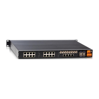
CLI, Telnet, WEB, SNMP and OPC-based network management. SICOM3024SM supports 2U 19 inch stable rack mounting for installation. There are four uplink redundant 1000M SFP interfaces and max 24 10Base-T/100Base-TX ports or 24 pairs of 100Base-FX(SM/MM)fiber ports in back panel. The redundant fiber or TP cable ring of 1000Mbit can be connected by redundant SFP interfaces with recovery time less than 50ms. - Page 12 SICOM3024SM Industrial Ethernet Switch User Manual Support various management software, easy entrance for user such as: WEB, CLI, TELNET, SNMP, OPC. 10Base-T/100Base-TX self-adaptive Ethernet connector (full/half duplex), MDI/MDI-X auto-connection 100Base-FX full duplex SM/MM redundant fiber connector Recovery time < 50ms increase the system reliability ...
-
Page 13: Packing List And Unpacking Check
Before opening the case, place it stably, pay attention to the direction of the packing case, and ensure its right side is facing upward, so as to prevent SICOM3024SM from falling apart after opening the case. If a hard object is used to unclench the case, do not overly extend the hard object into the case to avoid damage of the equipments inside the case. -
Page 15: Chapter 2 Performance Specifications
Chapter 2 Performance Specifications Chapter 2 Performance Specifications 2.1 System Specifications The system performance specifications of SICOM3024SM industrial Ethernet switch are shown in Table 2-1. Table 2-1 System Specs Specs Description 24×10Base-T/100Base-TX Quantity of RJ45 port Quantity of Gigabit redundant port 4×1000Base-SFP connectors... -
Page 16: Service Interface
SICOM3024SM Industrial Ethernet Switch User Manual DC110V(82V~185V),AC220V(85V~264),DC220V(120V~370V) Input power consumption: 35W Over-current Protection: build-in Physical dimensions (height´width´depth): 88 ㎜×482.6 ㎜×245 ㎜ Mounting mode: 19inch 2U stable rack mounting Heat removal method: Single-ribbed aluminum casing for heat Mechanical parameter dissipation without fan. -
Page 17: Service Function
QoS Priority IEEE 802.1p is the most popular priority solution in the LAN environment. SICOM3024SM series supports 802.1p, as well as IP TOS and DSCP, by which you can configure the port-based priority when the terminal does not support the above trhee configurations, and different priority for the ports is wanted. - Page 18 You can configure the TX and RX rate of all ports via the management software of SICOM3024SM. For port of 100Mbps, it can be set as 128K、 256K、 512K、 1M、 2M、 10M、50M、100M. For Gigabit port, it can be set as 100M、500M、1000M.
- Page 19 STP, and additional reduce the delay from block to forward, resuming the network ASAP. SICOM3024SM offers ACL(Access Control List) function to define the access rules by using the protocols of source or object MAC addresses. It can limit the network traffic, increases the networking performance and control the communication flow.
- Page 20 POE function SICOM3024SM support POE function. SICOM3024SM- POE board can be used as an independent module group. It supports max 6 FE ports with POE function. Each FE port is compliant with the power supply of IEEE802.3af standard. The module group can work under 24V and 48V.
-
Page 21: Chapter 3 Hardware Structure
3.2 Switch Structure 3.2.1 Case SICOM3024SM case is 19inches 2U stable rack mounting type structure. The entire unit has a six-side-enclosed structure, with protection class up to IP40. The case’s top side plates made of ribbed aluminum profile are a part of the heat dispersion system of the... -
Page 22: Front Panel
Discarding the traditional form of axial fan heat dispersion reduces power consumption of the entire unit and increases the stability of the system. The figuration of SICOM3024SM case is shown in Figure 3-2. Its contour dimension is 88 ㎜×482.6 ㎜×245 ㎜(height×width×thickness)... -
Page 23: Back Panel
100M for Gigabit indicator ports ports Figure 3-3 Front panel of SICOM3024SM 3.2.3 Back panel SICOM3024SM Industrial Ethernet switch front panel is show as Figure 3-4 AC power AC power 9.5mm-POE RS232 console input switch power input ports... - Page 24 SICOM3024SM Industrial Ethernet Switch User Manual Figure 3-5 SFP Plug and Play unit Gigabit SFP FX/TX Plug and play steps:Figure3-6 Insert SFP unit: There are two breaks on Fiber-port (LC) and one break on Ethernet port (RJ45) of SFP unit.
- Page 25 Chapter 3 Hardware Structure Optical Fiber interface SICOM3024SM offers 1 to 24 pairs of redundant 100Base-FX full duplex single mode or multi-mode optical fiber interface, with SC, FC and ST connector. Optical fiber interface should be used in pairs (TX and RX are a pair). TX interface is the transmitting end connected to the receiving end RX of the optical fiber interface of another remote switch;...
- Page 26 SICOM3024SM Industrial Ethernet Switch User Manual Condition State System state LED Blinking Switch operates normally Switch not operate Gigabit Optical fiber interface state LED(optical fiber interface G1、G2、G3、G4) Effective network connection has been established for the port. LINK Blinking Network activities are available for the port.
- Page 27 Chapter 3 Hardware Structure terminal locking screws Locking screws for power cables power ground +24V protection ground Figure 3-7 DC Power connection AC Power input terminal: AC220V: Single-phase three cores wire is used to for power connection. The terminal integrates a fuse socket which is convenient to fix new AC power fuse. Steps of replacing fuse are as follows: 1.
- Page 28 3-wire RS232. Users can use a network management cable with end bearing RJ45 plug and another end DB9F plug to connect the network management interface of SICOM3024SM with the 9-pin serial port of the control computer. Operating the local management software to set up SICOM3024SM by CLI.
- Page 29 Figure 3-10 CONSOLE wiring diagram Grounding SICOM3024SM Series Industrial Ethernet switch has a grounding screw hole in the rear panel. After connecting one terminal of grounding wire with the cold-pressing terminal, insert it to the grounding hole and screw it down with grounding screws. The other terminal of grounding wire connects to the ground.
-
Page 31: Chapter 4 Hardware Installation
4.2 Mainframe installation 4.2.1 Stable rack mounting SICOM3024SM industrial Ethernet switch can be installed in any standard 19 Inch Rack. Before mounting; make sure the following is ready: 1.Make sure there is enough space on the rack for SICOM3024SM installation 2.The power supply is available for SICOM3024SM. - Page 32 SICOM3024SM Industrial Ethernet Switch User Manual Figure 4-1 SICOM3024SM mounting drawing Cable wiring should meet the following requirements: 1. Before wiring, check whether the specifications, models and quantities of all cables comply with the construction drawing design and contract requirements.
- Page 33 Chapter 4 Hardware Installation the outlet part of cable channel or at turnings should be bundled and fixed. 8. If cables, power line and grounding conductor are laid in the same channel, cables, power line and grounding conductor should be not folded or blended together.
-
Page 35: Chapter 5 Test Methods
RUN indicator will keep flashing, showing the devices work well. 5.2 TP Port Test As shown in Figure 5-1, SICOM3024SM is powered on, connecting any two RJ45 ports to two PCs by straight-through cable and send Ping command to each other, they can... -
Page 36: Fiber Port Test
Figure 5-2 POE port test 5.4 Fiber Port Test As shown in Figure 5-3, two units of SICOM3024SM are connected to fiber chain network, connecting any one RJ45 port in each device to PCs by straight-through cable and sending Ping command to each other. They can both get command from each other without packet loss, and the LINK/ACT light of the fiber port should be always on.,... - Page 37 Chapter 5 Test methods Figure 5-3 Fiber port test PING commands example: Suppose the IP address for one computer is. 192.168.100.10 and the other one is 192.168.100.11, operate the “begin” menu on the one computer, and select the: operation” item. input “cmd” or ” command” , sending Ping 192.168.100.11 –l 1000 -t,...
-
Page 39: Chapter 6 Networking And Configurations
10Base-T/100Base-TX Ethernet RJ45 ports, each of which can provide link directly to the terminal devices, or to another industrial Ethernet switch/hub before terminal device as link share. SICOM3024SM has four (4) pairs of redundant fiber ports of 100Base-LX single mode or multimode. The redundant Gigabit fiber ports can form backbone redundant fiber ring of 1000M with recovery time less than 50ms. - Page 40 100M modules (plug and play) offer 6 ports, which can be RJ45 ports of 10Base-T/100Base-TX with POE function or 100M single mode/multimode fiber ports. The power supply for SICOM3024SM should be DC24V、 DC48V、 DC110V、 AC220V、 DC220V. Detailed configuration showing as table 6-1...
-
Page 41: Chapter 7 Web Management
7.1 Login Web Page Connecting the SICOM3024SM switch with a computer, input the IP address, eg. “192.168.0.2” in the IE browser, a window will appear as Figure 7-1, the default user name and password are admin and 123.click “OK”... -
Page 42: Device Status Display
SICOM3024SM Industrial Ethernet Switch User Manual Figure 7-2 Main Page 7.2 Device Status Display The menu of device status includes three submenus: Basic Information; Port state, Port Traffic Flow. 7.2.1 Basic Info Click “Basic info” and enter the interface as shown in Figure 7-3, which displays MAC... -
Page 43: Port State
Chapter 7 WEB Management 7.2.2 Port State Click “Port State” and enter the page as shown in Figure 7-4, which displays the link state, port speed, full/half duplex and flow control state etc. Figure 7-4 Port State 7.2.3 Port Traffic Flow Click “Port Flow”... -
Page 44: Device Basic Configuration
SICOM3024SM Industrial Ethernet Switch User Manual Figure 7-5 Port Flow 7.3 Device Basic Configuration In the menu of “Device Basic Configuration”, there are functions to configure IP address, device name, port, to change password, query software version and upgrade software, upload and download configuration, etc. -
Page 45: Configure Device Name
Chapter 7 WEB Management Figure 7-6 Configure IP Address 7.3.2 Configure Device Name Click the “Device Name” in the left menu and enter the page (as Figure 7-7), fill in the device name and click “Apply” button. Figure 7-7 Configure Device Name 7.3.3 Port Configuration Click the “Port Configuration”... -
Page 46: Change Password
SICOM3024SM Industrial Ethernet Switch User Manual Figure 7-8 Port Configuration 7.3.4 Change Password Click the “Change Password” in the left menu and enter the page (as Figure 7-9), enter old password and new password, click “Apply” to take effect. Figure 7-9 Change Password 7.3.5 Upgrade Software... -
Page 47: Software Version
Chapter 7 WEB Management detailed upgrading instructions, please refer to the Appendix D. Enter the main WEB page, click “upgrading bar” of basic configuration in navigation bar to enter into the upgrading page as shown in the following Figure: Figure 7-10 Upgrade Software Configure IP address, user name, password and software name of the FTP server, click “Apply”... -
Page 48: Configure Upload And Download
SICOM3024SM Industrial Ethernet Switch User Manual 7.3.7 Configure upload and download Click the “Upload/Download Configuration” in the left menu and enter the page (as Figure 7-12), enter server IP address and file name to be uploaded/downloaded, user name, password and click “Apply” to take effect. See the details of FTP configurations in “Appendix D”. -
Page 49: Port Traffic Flow
Chapter 7 WEB Management 7.4.1 Port Traffic Flow Click the “Port Flow” in the left menu and enter the page (as Figure 7-14), where you can configure the RX/TX speed of each port as the range of 128K、256K、512K、1M、 2M、10M、50M、100M for 100Mbps port and 100M、500M、1000M for Gigabit port. Click “Apply”... - Page 50 SICOM3024SM Industrial Ethernet Switch User Manual Figure 7-15 Add VLAN Figure 7-16 VLAN Configuration Figure 7-17 VLAN configuration successfully - 40 -...
-
Page 51: Port Mirroring
Chapter 7 WEB Management Figure 7-18 Untagged Port VLAN List 7.4.3 Port Mirroring Click the “Port Mirroring” in the left menu and enter the page (as Figure 7-19), select mirroring port from range of Module1-4/FE1~FE6、Module0/ GE1~GE4 and mirrored port from the range of TX、RX、TX&RX, click “Apply” to finish configuration. Figure 7-19 Port Mirroring - 41 -... -
Page 52: Port Trunking
SICOM3024SM Industrial Ethernet Switch User Manual Figure 7-20 Port Mirrored 7.4.4 Port Trunking Click the “Port Trunking” in the left menu and enter the page (as Figure 7-21), six trunk groups are supported. Each group allows max 4 ports. Choose the port from the froup, and Click , to add or delete trunked port. -
Page 53: Static Multicasting Address Table
Chapter 7 WEB Management Figure 7-22 Port trunking sample 7.4.5 Static Multicasting Address Table Click the “Static FDB Multicasting” in the left menu and enter the page (as Figure 7-23), select “enabled” and click “Apply”, Add static multicasting MAC address, VLAN ID and select port as shown in Figure 7-24, click “Apply”. - Page 54 SICOM3024SM Industrial Ethernet Switch User Manual Figure 7-23 Static Multicast address table Figure 7-24 Static Multicast filling sample - 44 -...
-
Page 55: Igmp-Snooping
Chapter 7 WEB Management Figure 7-25 Static Multicast configure successfully 7.4.6 IGMP-snooping Click the “IGMP-Snooping” in the left menu and enter the page (as Figure 7-26), enable IGMP-SNOOPING and auto query, click “Apply” to finish configuration. Click “IGMP-Snooping” in the left menu again to show configuration result as Figure 7-27. Note: Before enabling IGMP Snooping, static multicasting address table must be closed firstly. -
Page 56: Snmp Configuration
SICOM3024SM Industrial Ethernet Switch User Manual Figure 7-26 IGMP-SNOOPING Figure 7-27 IGMP Snooping configure successfully 7.4.7 SNMP Configuration Click the “SNMP Configuration” in the left menu and enter the page (as Figure 7-28), enable SNMP and set read/read&write name, enter TRAP server IP address, TRAP port no. -
Page 57: Alarm Configuration
Chapter 7 WEB Management Figure 7-28 SNMP configuration 7.4.8 Alarm configuration Click the “Port Alarm” in the left menu and enter the page (as Figure 7-29) to configure port and ring alarm, click “Apply” to take it effect. - 47 -... -
Page 58: Acl Configuration
SICOM3024SM Industrial Ethernet Switch User Manual Figure 7-29 Ring Alarm Configuration 7.4.9 ACL Configuration Click the “ACL Configuration” in the left menu and enter the page (as Figure 7-30), click “port configuration” and enter the page (as Figure 7-31), choose “anble/disable”... -
Page 59: Rstp Configuration
Chapter 7 WEB Management Figure 7-31 Port state configuration Figure 7-32 ACL protocol configuration 7.4.10 RSTP Configuration Click the “RSTP” in the left menu and enter the page (as Figure 7-33), select “RSTP” or “STP” to configure; fill out in the items “Spanning Tree Priority” (From 0 to 65535. The default is 32768 with the step of 4096), “Hello Time”... -
Page 60: Dt-Ring Configuration
SICOM3024SM Industrial Ethernet Switch User Manual “apply”. Note: RSTP can not be used together with DT-Ring. Figure 7-33 RSTP configuration 7.4.11 DT-Ring Configuration Click the “DT-Ring” in the left menu and enter the page (as Figure 7-34) to configure redundant ring based on port or VLAN. Click “Add” to enter page (such as Figure 7-35 and Figure 7-36). - Page 61 Chapter 7 WEB Management transferring port with the recovery time less than 50m. Configure four switches connecting by DT-Ring+: there are only two standby ports in two rings. The two standby ports are chosen from one ring. Figure 7-34 DT-Ring Figure 7-35 DT-Ring configuration based on VLAN - 51 -...
- Page 62 SICOM3024SM Industrial Ethernet Switch User Manual Figure 7-36 DT-Ring configuration based on ports - 52 -...
-
Page 63: Poe Configuration
Chapter 7 WEB Management Figure 7-37 DT-Ring configuration successfully 7.4.12 POE Configuration Click the “POE Configuration” in the left menu and enter the page (as Figure 7-38), select “Enable” or “Disable” for all ports. In the “Enable” state, POE function can work. The output power consumption is 5W, 10W and 15W, which can be chosen according to the power consumption of PD. -
Page 64: Qos Configuration
SICOM3024SM Industrial Ethernet Switch User Manual Figure 7-38 POE configuration 7.4.13 QoS Configuration Click the “QOS Configuration” in the left menu and enter the page (as Figure 7-39), enable QoS: weight (WRR) and preemption mode. Priority based on 802.1P or IO TOS, DSCP and port are for options. - Page 65 Figure 7-39 Qos configuration Click “802.1P Priority” and enter the page as figure 7-40. There are total 8 classes for 802.1P. SICOM3024SM supports four classes. You can select it and click “Apply”. Figure 7-40 802.1P priority configuration - 55 -...
- Page 66 SICOM3024SM Industrial Ethernet Switch User Manual Click “IPTOS Priority” and enter the page as figure 7-41. There are total 8 classes for IPTOS. SICOM3024SM supports four of them. You can select it and click “Apply”. Figure 7-41 IPTOS priority configuration Click “DSCP Priority”...
-
Page 67: Other Configuration
Chapter 7 WEB Management Figure 7-42 DSCP Priority configuration 7.4.14 Other configuration Click the “Other Configurations” in the left menu and enter the page (as Figure 7-43), which include two configurations of broadcasting storm control and MAC aging time. There are totally five options for broadcasting storm control: disable、1/2、 1/4、1/8、 1/16、... -
Page 68: Rmon Configuration
SICOM3024SM Industrial Ethernet Switch User Manual Figure 7-43 Other configuration 7.4.15 RMON Configuration RMON configurations include statistics, history, Alarm and Event. 7.4.15.1 RMON statistics Click “RMON Statistics” in the left menu to configure as figure 7-44. Enter index no.(from 1-65535) , owner serial no. (1-32), and select port no. (ifindex.0/1-4,1/1-6, 2/1-6, 3/1-6, 4/1-6). - Page 69 Chapter 7 WEB Management Figure 7-45 RMON History Configuration 7.4.15.3 RMON Alarm Click “RMON Alarm” in the left menu to configure as figure 7-46. Select alarm node in the MIB list and double click, the OID will finish automatically. In this page, enter index no.(from 1-65535) , owner serial no.
- Page 70 SICOM3024SM Industrial Ethernet Switch User Manual Figure 7-46 RMON Alarm configuration 7.4.15.4 RMON Event Click “RMON Event” in the left menu to configure as figure 7-47. Enter index no.(from 1-65535) , owner serial no. (1-32), event type (LOG/SNMP-trap/Log-and-Trap), event description (1-127), and event group (1-127). Click “Apply” to finish.
-
Page 71: Device Management
Chapter 7 WEB Management Figure 7-47 RMON Event configuration 7.5 Device Management Device Management includes reset, logout. 7.5.1 Restart Click “Reboot” in the left menu and enter the page as figure 7-48. Click “Reboot” to reset the device. Figure 7-48 Reboot 7.5.2 Logout Click “Logout”... -
Page 72: Load Default
SICOM3024SM Industrial Ethernet Switch User Manual 7.7 Load Default Click “Load Default ” in the left menu and enter the page as figure 7-51. Click “Load Default” to restore all default settings. Figure 7-51 Load Default - 62 -... -
Page 73: Appendix A Twisted-Pair And Pin Distribution
Appendix A Twisted-pair and Pin Distribution Appendix A Twisted-pair and Pin Distribution For the connection of 10Base-T/100Base-TX, the twisted-pair must have two pair cable. Each pair is distinguished with two different colors. For example, one strand is green, and the other is the alternate of green and white stripes. RJ-45 connector should be equipped at both ends of the cable. - Page 74 SICOM3024SM Industrial Ethernet Switch User Manual 10Base-T/100Base-TX is listed in the table A-1. Table A-1 Pin distribution of 10Base-T/100Base-TX MDI-X signal name MDI signal name Receiving data +(RD+) Output data+(TD+) Receiving data -(RD-) Output data -(TD-) Output data +(TD+) Receiving data+(RD+)...
-
Page 75: Appendix B Cable Type And Specifications
Appendix B Cable Type and Specifications Appendix B Cable Type and Specifications The cable type and specifications are shown as table B-1: Table B-1 Cable type and specification Connect Cable Type Max. length 10Base-T Cat 3,4 and 5 100 ohmUTP 100m RJ-45 100Base-TX... -
Page 77: Appendix C Glossary
Appendix C Glossary Appendix C Glossary Terminology Explanation Twisted-pair standard of Cat3, Cat4 and Cat5 in IEEE specification for 10Mbps 10Base-T Ethernet Twisted-pair standard of Cat5 or above in IEEE specification for 100Mbps Fast 100Base-TX Ethernet Fast Ethernet which uses one pair of multi-mode or single mode optical fiber to 100Base-FX transmit. - Page 78 SICOM3024SM Industrial Ethernet Switch User Manual IGMP IGMP means Internet Group Multicast Protocol. Use switches to set up the point to point connection among nodes in the LAN and Full Duplex allow them to receive and send data packet at the same time.
-
Page 79: Appendix D Ftp Application For Switch Software Update
Appendix D FTP Application for Switch Software Update You can use web management to upgrade SICOM3024SM software through switch by FTP protocol (Switch as Ftp client; PC as Ftp server) . Before update, you need to setup the Ftp server;FTP server is well-known software, and can be downloaded on the internet. - Page 80 SICOM3024SM Industrial Ethernet Switch User Manual Figure D-2 WFTPD configure user name and password 3. Type in your user name in New User window; here is “test”, click OK, as Figure D-3 Figure D-3 WFTPD configure user name 4. In Change Password window, type in the password in New Password and Verify area, for example ”test”, click OK.
- Page 81 Appendix D FTP Application for Switch Software Update allowed to update for the purpose of protecting software. We use WEB management software to upgrade it, steps: 1. Enter into WEB management page, click navigation bar to set Update, as Figure D-6: Figure D-6 Software Update 2....
- Page 82 SICOM3024SM Industrial Ethernet Switch User Manual 6. Wait for 30 seconds,start Web management system; click on navigation bar to check equipment basic information; software version; sure about the update successfully. As Figure D-9: Figure D-9 basic information Update is finish.
Need help?
Do you have a question about the SICOM3024SM and is the answer not in the manual?
Questions and answers