
Related Manuals for KYLAND Technology SICOM3024P


Summary of Contents for KYLAND Technology SICOM3024P
- Page 1 SICOM3024P Industrial Ethernet Switch Hardware Installation Manual Kyland Technology Co., Ltd. Publication Date: May. 2013 Version: V2.7 FAX: +86-10-88796678 Website: http://www.kyland.com E-mail: support@kyland.com...
- Page 2 SICOM3024P Industrial Ethernet Switch Hardware Installation Manual Disclaimer: Kyland Technology Co., Ltd. tries to keep the content of this manual as accurate and as updated as possible. This document is not guaranteed to be error-free, and we reserve the right to amend it without notice to users.
- Page 3 Notice for Safety Operation The product performs reliably as long as it is used according to the guidance. Artificial damage or destruction of the device should be avoided. Before using the device, read this notice carefully for personal and equipment safety. Please keep the manual for further reference. Kyland is not liable to any personal or equipment damage caused by violation of this notice.
- Page 4 Dispose of the device in accordance with relevant national provisions, preventing environmental pollution. In the following cases, please immediately shut down your power supply and contact your Kyland representative: Water gets into the equipment. Equipment damage or shell damage. ...
-
Page 5: Table Of Contents
Contents 1 Product Overview ........................1 2 Structure and Interface ........................ 4 2.1 Front Panel ..........................4 2.2 Rear Panel ..........................5 3 Switch Installation ........................7 3.1 Dimension Drawing ......................... 7 3.2 Mounting Modes and Steps ....................8 4 Cable Connection ........................10 4.1 10/100Base-T(X) Ethernet port ..................... -
Page 6: Product Overview
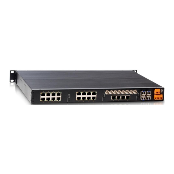
Product Overview 1 Product Overview SICOM3024P includes a series of managed industrial Ethernet switches tailored for power, rail transit, and coal mining industries. Capable of working properly in rugged environment, SICOM3024P conforms to IEC61850-3 and IEEE1613 standards and adopts internal modular design for flexible expansion. - Page 7 Product Overview SICOM3024P-2GX-16S/M SICOM3024P-2GX-12S/M-12T SICOM3024P-2GX-8S/M-16T SICOM3024P-2GX-8S/M SICOM3024P-2GX-4S/M-20T SICOM3024P-2GX-2S/M-22T SICOM3024P-2GX-24T SICOM3024P-4GE-24S/M SICOM3024P-4GE-16S/M-8T SICOM3024P-4GE-24T SICOM3024P-24S/M SICOM3024P-22S/M-2T SICOM3024P-20S/M-4T SICOM3024P-18S/M-6T SICOM3024P-16S/M-8T SICOM3024P-16S/M SICOM3024P-12S/M-12T SICOM3024P-12S/M-4T SICOM3024P-10S/M-14T SICOM3024P-8S/M-20T SICOM3024P-8S/M-16T SICOM3024P-8S/M SICOM3024P-6S/M-22T SICOM3024P-6S/M-18T SICOM3024P-4S/M-24T SICOM3024P-4S/M-20T SICOM3024P-4S/M-12T SICOM3024P-2S/M-26T SICOM3024P-2S/M-22T SICOM3024P-24T...
- Page 8 Product Overview SICOM3024P-16T Note: We reserve the right to amend the product information listed in the table above without notice. To obtain the latest information, contact our sales or technical support personnel.
-
Page 9: Structure And Interface
Structure and Interface 2 Structure and Interface Caution: It is recommended to purchase the port dustproof shield (optional) to keep ports clean and ensure switch performance. 2.1 Front Panel Figure 1 Front Panel Table 2 Description of Front Panel Identifier Description Alarm Alarm LED... -
Page 10: Rear Panel
Figure 2 shows the rear panel of SICOM3024P. The layout of Slot 1, Slot 2, and Slot 3 can be A, B, C, D, E, and the layout of Slot 4 can be F, G, H, I. The actual layout of these slots depends on the models (as listed in Table 1) you select. - Page 11 Structure and Interface Table 3 Description of Rear Panel Description 100Base-FX port 10/100Base-T(X) Ethernet port, RJ45 connector 10/100Base-T(X) RJ45 port speed LED (yellow) 10/100Base-T(X) RJ45 port connection status LED (green) 1000Base-X, 10/100/1000Base-T(X) SFP slot 1000Base-X, 10/100/1000Base-T(X) SFP slot connection status LED (green, indicating the status of the upper slot) 1000Base-X, 10/100/1000Base-T(X) SFP slot speed LED (yellow, indicating the speed of the upper slot)
-
Page 12: Switch Installation
Switch Installation 3 Switch Installation 3.1 Dimension Drawing Figure 3 Dimension Drawing (unit: mm) Caution: As part of the heat dissipation system, the switch housing becomes hot during operation. Please use caution when coming in contact and avoid covering the switch housing when the switch is running. ... -
Page 13: Mounting Modes And Steps
Switch Installation 3.2 Mounting Modes and Steps The series switches support rack mounting by front/rear panel. The following uses mounting by front panel as an example to describe mounting steps. The steps for mounting by rear panel are similar to those for mounting by front panel. Before installation, make sure that the following requirements are met. - Page 14 Switch Installation Figure 5 Installing Mounting Brackets Mounting Step 1: Select the mounting position for the device and guarantee adequate space and heat dissipation for it (dimensions: 440mm×44mm×322.5mm). Step 2: Move the switch in direction 1 until the screw holes for securing the mounting brackets to rack posts are in alignment with the corresponding holes in the rack posts.
-
Page 15: Cable Connection
Cable Connection 4 Cable Connection 4.1 10/100Base-T(X) Ethernet port 10/100Base-T(X) Ethernet port is equipped with RJ45 connector. The port is self-adaptive. It can automatically configure itself to work in 10M or 100M state, full or half duplex mode. The port can also adapt to MDI or MDI-X connection automatically. -
Page 16: 100Base-Fx Port
Cable Connection Note: The color of the cable for RJ45 connector meets the 568B standard: 1-orange and white, 2-orange, 3-green and white, 4-blue, 5-blue and white, 6-green, 7-brown and white, and 8-brown. 4.2 100Base-FX Port 100Base-FX port is equipped with ST/SC/FC connector, and each port consists of TX (transmit) port and RX (receive) port, as shown in Figure 9. - Page 17 Cable Connection The following table lists the pin definitions of the 10/100/1000Base-T(X) RJ45 port. Table 5 Pin Definitions of 10/100/1000Base-T(X) RJ45 Port MDI-X Signal MDI Signal Transmit/Receive Data (TRD1+) Transmit/Receive Data (TRD0+) Transmit/Receive Data (TRD1-) Transmit/Receive Data (TRD0-) Transmit/Receive Data (TRD0+) Transmit/Receive Data (TRD1+) Transmit/Receive Data (TRD3+) Transmit/Receive Data (TRD2+)
-
Page 18: 1000Base-X, 10/100/1000Base-T(X) Sfp Slot
SFP optical/electrical module into the slot and connecting cable properly. The following table lists the Gigabit SFP optical/electrical modules (optional) supported by the series switches. Table 6 Gigabit SFP Optical/Electrical Modules for SICOM3024P Center Transmission Model... -
Page 19: Gigabit Sfp Electrical Module
Cable Connection How to Connect the SFP Optical Module Insert the SFP optical module into the SFP slot in the switch, and then plug the optical fiber into the TX port and RX port of the SFP module. Figure 14 Connecting the Gigabit SFP Optical Module How to Determine the RX Port and TX Port of Gigabit SFP Optical Module 1. -
Page 20: Console Port
Cable Connection Figure 16 Connecting the Gigabit SFP Electrical Module 4.5 Console Port There is a Console port on the front panel of the switch, as shown in Figure 17. Connect the 9-pin serial port of a PC to the console port of the switch with a DB9-RJ45 console cable. You can configure, maintain, and manage the switch by running Hyper Terminal in the Windows OS of a computer. -
Page 21: Grounding
Cable Connection Table 7 Pin Definitions of DB9 Port (9-Pin Serial Port) and RJ45 Port (Console Port) DB9 Port (9-Pin Serial Port) RJ45 Port (Console Port) Signal Signal RXD (Receive data) TXD (Transmit data) TXD (Transmit data) RXD (Receive data) GND (Grounding) GND (Grounding) 4.6 Grounding... - Page 22 Cable Connection 5-pin 5.08mm-spacing plug-in terminal block Figure 20 shows the pin numbers of the 5-pin 5.08mm-spacing plug-in terminal block. Figure 20 5-Pin 5.08mm-Spacing Plug-in Terminal Block Table 8 lists the pin definitions of the 5-pin 5.08mm-spacing plug-in terminal block. Table 8 Pin Definitions of 5-Pin 5.08mm-Spacing Plug-in Terminal Block Signal DC Definition...
-
Page 23: Alarm Terminal Block
Cable Connection Figure 21 Cable Connection of 5-Pin 5.08mm-Spacing Plug-in Terminal Block Caution: The device supports 24DC, 48DC, and 220AC/DCW power input. Before connecting the device to power supply, make sure that the power input meets the power requirement. If connected to an incorrect power input, the device may be damaged. - Page 24 Cable Connection Pin 1 and pin 2 are normally-open contacts; pin 2 and pin 3 are normally-closed contacts. When the switch works properly, pin 1 and pin 2 are closed, pin 2 and pin 3 are open; when an alarm occurs, pin 1 and pin 2 are open;...
-
Page 25: Leds
LEDs 5 LEDs Table 9 Front Panel LEDs State Description Blinking The CPU operates properly. Running LED The CPU does not start up or the CPU operates abnormally or the device is starting up. An alarm occurs. Alarm LED No alarm occurs. Power 1 is connected and operates properly. - Page 26 LEDs Table 10 Rear Panel LEDs State Description LED 1 and LED 2 indicate the status of the lower gigabit SFP slot, while LED 3 and LED 4 indicate the status of the upper gigabit SFP slot. optical module 1000M working state (1000Base-X) 1000Base-X, inserted 100M working state (100Base-FX) or no connection...
-
Page 27: Switch Access
Switch Access 6 Switch Access You can access the switch in any of the following ways: 6.1 Access through Console Port Step 1: Connect the console port of the switch to the 9-pin serial port of a PC with the delivered DB9-RJ45 console cable. - Page 28 Switch Access Step 4: Connect the communication port in use, as shown in Figure 24. Figure 24 Selecting the Communication Port in Use Note: confirm communication port use, right-click Computer] click [Property]→[Hardware]→[Device Manager]→[Port] to view the communication port. Step 5: Set port parameters (Bits per second: 9600, Data bits: 8, Parity: None, Stop bits: 1, and Flow control: None), as shown in Figure 25.
-
Page 29: Access Through Telnet
Switch Access Table 11 CLI Commands View Command Description User view SWITCH>enable Enter the management view. Management view SWITCH#show interface Query the IP address of the switch. Management view SWITCH#show version Query the version of the switch. Management view SWITCH#reboot Restart the switch. -
Page 30: Basic Features And Specifications
Basic Features and Specifications 7 Basic Features and Specifications Power Requirements Power Identifier Rated Voltage Range Maximum Voltage Range 24DC 24VDC 18-36VDC 48DC 48VDC 36-72VDC 220AC/DCW 100-240VAC, 50/60Hz; 110-220VDC 85-264VAC/77-300VDC Power terminal 5-pin 5.08mm-spacing plug-in terminal block Rated Power Consumption Rated Power Consumption 35W (MAX) Physical Characteristics Housing...
Need help?
Do you have a question about the SICOM3024P and is the answer not in the manual?
Questions and answers