Table of Contents
Advertisement
Quick Links
Advertisement
Table of Contents

Subscribe to Our Youtube Channel
Related Manuals for AXIOMTEK Mano831 Series


Summary of Contents for AXIOMTEK Mano831 Series
- Page 1 MANO831 Series ® Intel Atom D2550 Mini ITX Motherboard User’s Manual...
- Page 2 Axiomtek does not make any commitment to update the information in this manual. Axiomtek reserves the right to change or revise this document and/or product at any time without notice. No part of this document may be reproduced, stored in a retrieval system, or transmitted, in any form or by any means, electronic, mechanical, photocopying, recording, or otherwise, without the prior written permission of Axiomtek Co., Ltd.
-
Page 3: Esd Precautions
Wear a wrist-grounding strap, available from most electronic component stores, when handling boards and components. Trademarks Acknowledgments Axiomtek is a trademark of Axiomtek Co., Ltd. ® Windows is a trademark of Microsoft Corporation. AMI is a trademark of American Megatrend Inc. -
Page 4: Conventions Used In This Manual
Conventions Used in This Manual To make sure that you perform certain tasks properly, take note of the following symbols used throughout this manual. Information to prevent injury to yourself when trying to complete a task. Warning Information to prevent damage to the components when trying to complete a task. -
Page 5: Table Of Contents
Table of Contents Disclaimers ..................... ii ESD Precautions ................... iii Conventions Used in This Manual ............... iv Chapter 1 Introduction ..........1 Features ....................1 Specifications ..................2 Utilities Supported ................3 Block Diagram ..................4 Chapter 2 Board and Pin Assignments ....5 Board Layout .................. - Page 6 Chapter 3 Hardware Installation ......21 Motherboard Overview ..............21 3.1.1 Placement Direction .................. 21 3.1.2 Screw Holes ....................21 Central Processing Unit (CPU) ............22 3.2.1 CPU Location .................... 22 3.2.2 The CPU Heatsink and Fan ..............23 System Memory ................. 24 3.3.1 Overview ....................
-
Page 7: Chapter 1 Introduction
MANO831 Mini ITX Board Chapter 1 Introduction ® Atom™ processor D2550 The MANO831 is designed to unleash the power of the new Intel ® which supports the new revolutionary two–chip layout. The Intel Cedarview processor also provides additional flexibility and upgradeability with two slots of single channel DDR3 memory at 1066 MHz supporting up to 4GB maximum. -
Page 8: Specifications
MANO831 Mini ITX Board Specifications ® Intel Atom D2550 1.86GHz dual-core processor. System Chipset ® Intel NM10. BIOS AMI 16Mb SPI ROM. System Memory D2550: Two 204-pin SO-DIMM sockets support up to 4GB single channel DDR3 1066/800MHz SDRAM. -
Page 9: Utilities Supported
MANO831 Mini ITX Board Form Factor Mini ITX form factor. All specifications and images are subject to change without notice. Note Utilities Supported Chipset driver Ethernet driver Graphics driver Audio driver TPM driver ... -
Page 10: Block Diagram
MANO831 Mini ITX Board Block Diagram Introduction... -
Page 11: Board And Pin Assignments
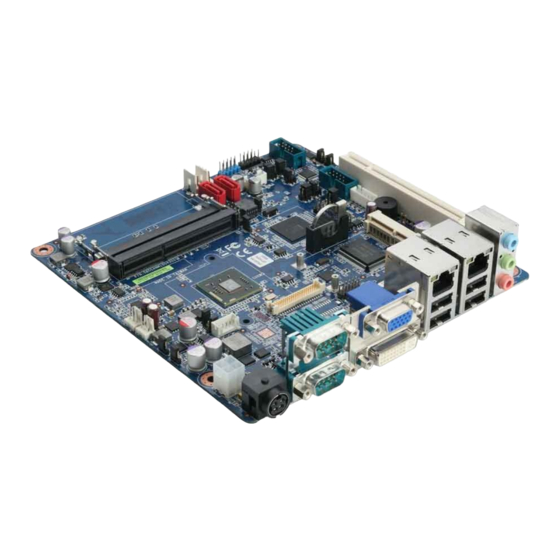
MANO831 Mini ITX Board Chapter 2 Board and Pin Assignments Board Layout Top View Board and Pin Assignments... - Page 12 MANO831 Mini ITX Board Bottom View Board and Pin Assignments...
-
Page 13: Jumper Settings
And remove jumper clip from 2 jumper pins to open. The following illustration shows how to set up jumper. Before applying power to MANO831 Series, please make sure all of the jumpers are in factory default position. Below you can find a summary table and onboard default settings. -
Page 14: Clear Cmos (Jcmos1)
MANO831 Mini ITX Board 2.2.1 Clear CMOS (JCMOS1) This jumper allows you to clear the Real Time Clock (RTC) RAM in CMOS. You can clear the CMOS memory of date, time, and system setup parameters by erasing the CMOS RTC RAM data. The onboard button cell battery powers the RAM data in CMOS, which includes system setup information such as system passwords. -
Page 15: Com4 Rs-232/422/485 Mode Setting (Jp4, Jp5, Jp6)
MANO831 Mini ITX Board 2.2.3 COM4 RS-232/422/485 Mode Setting (JP4, JP5, JP6) This jumper allows you to select the operation mode of COM port 4. Function Setting JP4 1-3, 2-4 close RS-232 mode JP5 1-2 close (Default) JP6 1-3, 2-4 close JP4 3-5, 4-6 close RS-422 mode JP5 3-4 close... -
Page 16: At/Atx Power Mode Selection (Jds6)
MANO831 Mini ITX Board 2.2.7 AT/ATX Power Mode Selection (JDS6) This jumper allows you to select AT mode or ATX mode. Function Setting AT mode 1-2 close ATX mode (Default) 2-3 close 2.2.8 SATA Port 2 Function Selection (JSATA_SEL1) Function Setting 1-2 close SATA HDD (Default) -
Page 17: Connectors
MANO831 Mini ITX Board Connectors Signals go to other parts of the system through connectors. Loose or improper connection might cause problems, please make sure all connectors are properly and firmly connected. Here is a summary table which shows all connectors on the hardware. Connector Description COM1, COM2... -
Page 18: Rear Panel Connectors
MANO831 Mini ITX Board 2.3.1 Rear Panel Connectors 2.3.2 FAN Connectors (CPU_FAN1 and SYS_FAN1) The fan connectors support cooling fans of 280mA (3.36 W max.) at 4800rpm or a total of 1A (12W max.) at +12V. Connect the fan cables to the fan connectors on the motherboard, making sure that the black wire of each cable matches the ground pin of the connector. -
Page 19: Front Panel Connector (F_Panel)
MANO831 Mini ITX Board 2.3.3 Front Panel Connector (F_PANEL) This connector is for a chassis-mounted front panel I/O module that supports power on/reset switch and HDD/power LED indicate. Signal HDD_LED+ SUPLED SATA_LED# PANSWIN# SRST# ATX Power Button/Soft-off Button (Pin 6-8 PWRBT) This 2-pin connector is for the system power button. -
Page 20: Atx Power Connector (Atx12V)
MANO831 Mini ITX Board 2.3.4 ATX Power Connector (ATX12V) This connector is for ATX power supply plug. The power supply plug is designed to fit this connector in only one orientation. Find the proper orientation and push down firmly until the connector completely fit. Signal Signal +12V... -
Page 21: Internal Audio Connector (Aafp1)
MANO831 Mini ITX Board 2.3.6 Internal Audio Connector (AAFP1) This connector is for a chassis-mounted front panel audio I/O module that supports either HD Audio or legacy AC ‘97 (optional) audio standard. Connect one end of the front panel audio I/O module cable to this connector. Signal MIC2_L MIC2_R... -
Page 22: Tpm Connector (Tpm1)
MANO831 Mini ITX Board 2.3.8 TPM Connector (TPM1) This connector is for support TPM. Signal Signal CK_33M LFRAME# PLTRST# SMB_DATA LAD3 LAD2 LAD1 LAD0 3VSB SERIRQ CLKRUN# LPCPD# SMB_CLK 2.3.9 Serial ATA Connectors (SATA1 and SATA2) These connectors support SATA 2.0 and are for hard disk drives. Signal SATA_TXP2 SATA_TXN2... -
Page 23: Usb Connectors (Usb45 And Usb6)
MANO831 Mini ITX Board 2.3.10 USB Connectors (USB45 and USB6) These connectors are for USB 2.0 ports. Connect the optional USB module cable to any of these connectors, then install the module to a slot opening at the back of the system chassis. -
Page 24: Lvds Connectors (Jlvds1 And Jlvds2)
MANO831 Mini ITX Board 2.3.12 LVDS Connectors (JLVDS1 and JLVDS2) The JLVDS1 is for 18/24-bit single channel LVDS panel. Signal Signal +3.3V +3.3V LVDS DDC CLK LVDS DDC DATA LVDS_TX1_P LVDS_TX0_P LVDS_TX1_N LVDS_TX0_N LVDS_TX3_P LVDS_TX2_P LVDS_TX3_N LVDS_TX2_N LVDS_CLK_P LVDS_CLK_N +12V +12V The JLVDS2 is for 18/24-bit dual channel LVDS panel. -
Page 25: Lvds Backlight Connector (Jbkl1)
MANO831 Mini ITX Board 2.3.13 LVDS Backlight Connector (JBKL1) The connector is for the control of internal LVDS brightness. Signal +12V Backlight Enable Backlight Ctrl 2.3.14 GPIO Connector (JDIO1) This connector is for GPIO function. Signal Signal SIO_GPIO0 SIO_GPIO4 SIO_GPIO1 SIO_GPIO5 SIO_GPIO2 SIO_GPIO6... - Page 26 MANO831 Mini ITX Board This page is intentionally left blank. Board and Pin Assignments...
-
Page 27: Chapter 3 Hardware Installation
MANO831 Mini ITX Board Chapter 3 Hardware Installation Take note of the following precautions before you install motherboard components or change any motherboard settings. Unplug the power cord from the wall socket before touching any component. Use a grounded wrist strap or touch a safely grounded object or a metal object, such as the power supply case, before handling components to avoid Caution damaging them due to static electricity. -
Page 28: Central Processing Unit (Cpu)
MANO831 Mini ITX Board Place this side towards the rear of the chassis. Central Processing Unit (CPU) ® The motherboard comes with onboard Intel Atom™ D2550 processor. 3.2.1 CPU Location Locate the CPU on the motherboard. Hardware Installation... -
Page 29: The Cpu Heatsink And Fan
MANO831 Mini ITX Board 3.2.2 The CPU Heatsink and Fan ® Intel Atom™ processor requires a specially designed heatsink and fan assembly to ensure optimum thermal condition and performance. CPU FAN Do not forget to connect the fan cables to the fan connectors. Insufficient air flow inside the system may damage the motherboard components. -
Page 30: System Memory
MANO831 Mini ITX Board System Memory 3.3.1 Overview The motherboard comes with two 204-pin Double Data Rate 3 (DDR3) Small Outline Dual Inline Memory Modules (SO-DIMM) sockets. A DDR3 module has the same physical dimensions as a DDR SO-DIMM but has a 204-pin footprint compared to the 204-pin DDR2 DIMM. -
Page 31: Memory Configurations
MANO831 Mini ITX Board 3.3.2 Memory Configurations You may install 1GB and 2GB unbuffered non-ECC DDR3 SO-DIMMs into the SO-DIMM sockets using the memory configurations in this section. IF you installed two 2GB memory modules, the system may detect less than 3GB of total memory because of address space allocation for other critical functions. - Page 32 MANO831 Mini ITX Board Firmly insert the SO-DIMM into the socket until the retaining clips snap back in place and the SO-DIMM is properly seated. DDR3 SO-DIMM notch Retaining clip A DDR3 SO-DIMM is keyed with a notch so that it fits in only one direction.
-
Page 33: Removing A So-Dimm
MANO831 Mini ITX Board 3.3.4 Removing a SO-DIMM Simultaneously press the retaining clips downward to unlock the SO-DIMM. Remove the SO-DIMM from the socket. DDR3 SO-DIMM notch Retaining clip Support the SO-DIMM lightly with your fingers when pressing the retaining clips. The SO-DIMM might get damaged when it flips out with extra force. -
Page 34: Configuring An Expansion Card
MANO831 Mini ITX Board 3.4.2 Configuring an Expansion Card After installing the expansion card, configure it by adjusting the software settings. Turn on the system and change the necessary BIOS settings, if any. See Chapter 5 for information on BIOS setup. Assign an IRQ to the card if needed. -
Page 35: Compactflash Tm Socket
MANO831 Mini ITX Board 3.4.5 CompactFlash Socket This motherboard supports one CompactFlash card socket and its location is on bottom side of the PCB. The following figure shows a CompactFlash card installed on the CompactFlash socket. Hardware Installation... - Page 36 MANO831 Mini ITX Board This page is intentionally left blank. Hardware Installation...
-
Page 37: Chapter 4 Hardware Description
Make sure all correct settings are arranged for your installed microprocessor to prevent the CPU from damages. BIOS The MANO831 Series uses AMI Plug and Play BIOS with a single 16Mbit SPI Flash. System Memory The MANO831 Series supports two 204-pin DDR3 SO-DIMM sockets for a maximum memory of 4GB DDR3 SDRAMs. -
Page 38: I/O Port Address Map
MANO831 Mini ITX Board I/O Port Address Map ® The Intel Atom D2550 processors communicate via I/O ports. Total 1KB port addresses are available for assigning to other devices via I/O expansion cards. Hardware Description... - Page 39 MANO831 Mini ITX Board Hardware Description...
-
Page 40: Interrupt Controller (Irq) Map
MANO831 Mini ITX Board Interrupt Controller (IRQ) Map The interrupt controller (IRQ) mapping list is shown as follows: Hardware Description... - Page 41 MANO831 Mini ITX Board Hardware Description...
- Page 42 MANO831 Mini ITX Board Hardware Description...
-
Page 43: Memory Map
MANO831 Mini ITX Board Memory Map The memory mapping list is shown as follows: Hardware Description... - Page 44 MANO831 Mini ITX Board This page is intentionally left blank. Hardware Description...
-
Page 45: Ami Bios Setup Utility
MANO831 Mini ITX Board Chapter 5 AMI BIOS Setup Utility The AMI UEFI BIOS provides users with a built-in setup program to modify basic system configuration. All configured parameters are stored in a flash chip to save the setup information whenever the power is turned off. - Page 46 MANO831 Mini ITX Board Hot Keys Description Left/Right The Left and Right <Arrow> keys allow you to select a setup screen. The Up and Down <Arrow> keys allow you to select a setup screen or Up/Down sub-screen. The Plus and Minus <Arrow> keys allow you to change the field value of a +...
-
Page 47: Main Menu
MANO831 Mini ITX Board Main Menu When you first enter the setup utility, you will enter the Main setup screen. You can always return to the Main setup screen by selecting the Main tab. System Time/Date can be set up as described below. -
Page 48: Advanced Menu
MANO831 Mini ITX Board Advanced Menu Launch PXE OpROM Enable or disable the boot ROM function of the onboard LAN chip when the system boots The Advanced menu also allows users to set configuration of the CPU and other system devices. - Page 49 MANO831 Mini ITX Board PCI Subsystem Settings You can use this screen to select options for PCI subsystem settings, and change the value of the selected option. A description of the selected item appears on the right side of the screen.
- Page 50 MANO831 Mini ITX Board ACPI Settings You can use this screen to select options for the ACPI configuration, and change the value of the selected option. A description of the selected item appears on the right side of the screen.
- Page 51 MANO831 Mini ITX Board Trusted Computing This screen provides function for specifying the Trusted Platform Module (TPM) settings. TPM Support Enable or disable TPM support. Current Status Information Display current TPM status information. AMI BIOS Setup Utility...
- Page 52 MANO831 Mini ITX Board CPU Configuration This screen shows the CPU information. Hyper-threading Use this item to enable or disable Hyper-Threading Technology, which makes a single physical processor perform multi-tasking function as two logical ones. Execute Disable Bit Enable or disable the No-Execution Page Protection Technology. Limit CPUID Maximum You can enable this item to let legacy operating systems boot even without support for CPUs with extended CPU ID functions.
- Page 53 MANO831 Mini ITX Board IDE Configuration In this Configuration menu, you can see the currently installed hardware in the IDE ports. During system boot up, the BIOS automatically detects the presence of SATA devices. SATA Controller(s) Enable or disable SATA controller(s). Configure SATA as Determine how SATA controller(s) operate.
- Page 54 MANO831 Mini ITX Board USB Configuration You can use this screen to select options for the USB Configuration, and change the value of the selected option. A description of the selected item appears on the right side of the screen.
- Page 55 MANO831 Mini ITX Board Super IO Configuration You can use this screen to select options for the Super IO Configuration, and change the value of the selected option. A description of the selected item appears on the right side of the screen.
- Page 56 MANO831 Mini ITX Board Hardware Monitor Use this screen for Smart Fan configuration and hardware health status monitoring. This screen displays the temperature of system and CPU, cooling fan speed in RPM and system voltages (VCORE, +12V, +5V, +5VSB, etc). Smart Fan Function Enable or disable Smart Fan.
- Page 57 MANO831 Mini ITX Board Serial Port Console Redirection Console Redirection Enable or disable console redirection for Microsoft Windows Emergency Management Services (EMS). Console Redirection Settings Display console redirection settings screen. AMI BIOS Setup Utility...
- Page 58 MANO831 Mini ITX Board PPM Configuration Use this screen for PPM configuration. CPU C state Report Enable or disable CPU C state report to OS. AMI BIOS Setup Utility...
-
Page 59: Chipset Menu
MANO831 Mini ITX Board Chipset Menu The Chipset menu allows users to change the advanced chipset settings. You can select any of the items in the left frame of the screen to go to the sub menus: ► Host Bridge ►... - Page 60 MANO831 Mini ITX Board Host Bridge This screen allows users to set Host Bridge parameters. Memory Frequency and Timing Display memory frequency and timing settings screen. Intel IGD Configuration Display internal graphics configuration screen. Memory Information Display detected memory information. AMI BIOS Setup Utility...
- Page 61 MANO831 Mini ITX Board Memory Frequency and Timing MRC Fast Boot Enable or disable MRC fast boot function. Max TOLUD Maximum value of TOLUD. Dynamic assignment would adjust TOLUD automatically based on largest MMIO length of installed graphic controller. AMI BIOS Setup Utility...
- Page 62 MANO831 Mini ITX Board Intel IGD Configuration Boot Display Type Select the video device which will be activated during POST. LVDS2 Control Enable and disable LVDS2 control. LCD Panel Type Select LCD panel type for LVDS port. Color Depth Select the panel color depth.
- Page 63 MANO831 Mini ITX Board South Bridge For items marked with “”, please press <Enter> for more options. TPT Devices ® Enable or disable Intel IO controller hub (TPT) devices. PCI Express Root Port 4 Control the PCI Express root port. Onboard LAN1/2 Controller Enable or disable onboard LAN1/LAN2 controller.
-
Page 64: Boot Menu
MANO831 Mini ITX Board Boot Menu The Boot menu allows users to change boot options of the system. Setup Prompt Timeout Number of seconds to wait for setup activation key. 65535(0xFFFF) means indefinite waiting. Bootup NumLock State Use this item to select the power-on state for the keyboard NumLock. ... - Page 65 MANO831 Mini ITX Board Boot Option Priorities These are settings for boot priority. Specify the boot device priority sequence from the available devices. Boot Option #1..#2 These items are used to form the boot order and are dynamically generated. They represent either a legacy BBS (BIOS Boot Specification) class of devices or a native EFI boot entry.
-
Page 66: Security Menu
MANO831 Mini ITX Board Security Menu The Security menu allows users to change the security settings for the system. Administrator Password This item indicates whether an administrator password has been set (installed or uninstalled). User Password This item indicates whether an user password has been set (installed or uninstalled). AMI BIOS Setup Utility... -
Page 67: Save & Exit Menu
MANO831 Mini ITX Board Save & Exit Menu The Save & Exit menu allows users to load your system configuration with optimal or fail-safe default values. Save Changes and Exit When you have completed the system configuration changes, select this option to leave Setup and return to Main Menu. - Page 68 MANO831 Mini ITX Board Discard Changes Select this option to quit Setup without making any permanent changes to the system configuration. Select Discard Changes from the Save & Exit menu and press <Enter>. Select Yes to discard changes. Restore Defaults It automatically sets all Setup options to a complete set of default settings when you select this option.
Need help?
Do you have a question about the Mano831 Series and is the answer not in the manual?
Questions and answers