
Related Manuals for Secure SRT321


Summary of Contents for Secure SRT321
- Page 1 SRT321 User and Installation Instructions Electronic Room Thermostat & Temperature Sensor (Tx) - Z-Wave...
- Page 3 The SRT321 will only operate when 2 x AAA batteries have been fitted. This document provides information specific to the Z- wave technology implemented on SRT321, to ensure correct interoperability between third party devices.
-
Page 4: User Instructions
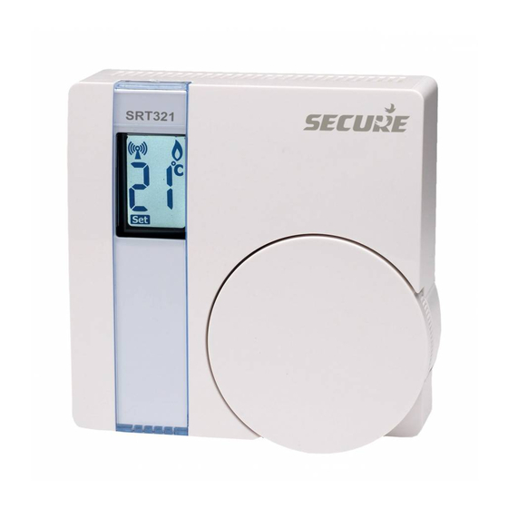
USER INSTRUCTIONS The Secure SRT321 thermostat uses the latest control technology to provide extremely accurate temperature control which will help to keep your energy usage as low as possible without affecting your comfort levels. In fact comfort levels may well be improved as the control accuracy should ensure that the room does not ‘overheat’... - Page 5 7 seconds before returning to the set temperature. The aerial symbol complete with radio wave symbols in the display of the SRT321 thermostat indicates that it is communicating satisfactorily with the rest of the system. A flashing radio wave indicates a loss of communication.
- Page 6 A radio mast symbol with no radio waves indicates that the SRT321 has not been signed on to enable it to communicate with the Z-Wave system. In this case you may wish to contact the Installer as the indication is that the product has not been commissioned when the installation took place.
- Page 7 Battery Replacement The SRT321 runs on 2 x type AAA (Alkaline) non rechargeable batteries and is designed to give a battery life of approximately two years – under normal usage conditions. Battery should When the batteries are be changed nearing the end of their life...
- Page 8 Remove the old batteries and replace them with two new AAA size alkaline batteries ensuring that they are fitted correctly as indicated by the terminal markings in the battery compartments. Once the batteries are fitted, re-fit the thermostat to the wall plate by engaging with the lugs at the top of the wall plate and push the thermostat into position.
- Page 9 Avoid installing the thermostat against or behind any large metal surfaces which could interfere with the radio signals. The SRT321 should be mounted on an internal wall approximately 1.5 metres from floor level using the wall plate provided and should be in a position away from draughts, direct heat and sunlight.
- Page 10 Offer the plate to the wall in the position where the SRT321 is to be mounted and mark the fixing positions through the slots in the wall plate. Drill and plug the wall, then secure the plate into position. The slots in the wall plate will compensate for any misalignment of the fixings.
- Page 11 DIL switch numbers 7 and 8 should be Ÿ SWITCH CONFIGURATION SRT321 set as diagram opposite. For Gas boilers set the TPI setting to 6 Ÿ cycles per hour. (Default setting) For Oil boilers set the TPI setting to 3 Ÿ...
- Page 12 P after the character and a failure will be displayed with an F. If no response has been received from a 3rd party unit within the time-out period, the SRT321 will report a failure. To exit installation mode, change DIL switch 1 to its...
- Page 13 Will restore all parameters back to factory default settings Associate Control Unit 3, 6 Disassociate Control Unit 3, 6 Controller Shift 3 This function allows the installer to manually relinquish the primary controller role of the SRT321 to become a secondary or inclusion controller.
- Page 14 2 If an outcome is not received within 5sec the SRT321 will report a failure. 3 On selecting this function the installer has 60s to initiate a 3rd party unit before the SRT321 times out and reports a failure 4 Nodes supporting ‘Thermostat Mode Command Class’...
- Page 15 7 In the instance both ‘Thermostat Mode’ and ‘Binary Switch’ Command Class are supported, the SRT321 will default to use the ‘Thermostat Mode Command Class’. Network Update Scheme When the unit is a secondary or inclusion controller with a SUC/SIS present, the unit will request network updates once every 23 hours.
- Page 16 Thermostat Mode This Command Class will use thermostat modes Command Class ‘OFF’ and ‘HEAT’ to control a 3rd party unit. The SRT321 will be associated in group 1. Binary Switch This will use SET commands to control a 3rd Command Class Party unit, and be associated in group 2.
- Page 17 The SRT321 will accept Set Point SET commands if the set point type matches the thermostat type configuration. SRT321 will send a Set Point REPORT in response to a Set Point GET message or unsolicited message can be sent to nodes in Group 4 when the set temperature is changed locally on the SRT321.
- Page 18 Association The following association groups are supported: Command Class Group 1 - Nodes controlled by Thermostat Mode SET command. Group 2 - Nodes controlled by Binary Switch SET command. Group 3 - Nodes to receive unsolicited Battery Level Reports or Low Battery Warnings. Group 4 - Nodes to receive Thermostat Set Point Reports.
- Page 19 Wake up Interval: 15 Minutes (min) Ÿ Temperature Report: Δ0.5°C (min) and/or Wake up (15 Mins) Ÿ Thermostat specifications SRT321 Power supply: 2 x AAA alkaline batteries Temperature accuracy: +/- 0.5°C Transmitter frequency:...
- Page 20 Cewe Instrument AB Box 1006 611 31 Nyköping Tel: +46 8 600 80 60 Email: info@securetogether.eu Web Site: www.securetogether.eu Leaflet Number P84073 Issue 1...
Need help?
Do you have a question about the SRT321 and is the answer not in the manual?
Questions and answers