Advertisement
Table of Contents
- 1 User Instructions
- 2 Battery Replacement
- 3 Installer Instructions
- 4 DIL Switch Settings
- 5 TPI Temperature Control Software
- 6 Installation Mode
- 7 Wireless System Setup
- 8 Navigating the Setup Menu
- 9 Learn Mode
- 10 Positioning the SRT323 Room Thermostat
- 11 Fitting the Wall Plate
- 12 Mounting the Thermostat Onto the Wall Plate
- 13 Wiring Guide
- 14 SRT323 Thermostat – Internal Wiring Diagram
- 15 Supported Device and Command Classes
- 16 Thermostat Specifications SRT323
- Download this manual
Advertisement
Table of Contents

Related Manuals for Secure SRT323


Summary of Contents for Secure SRT323
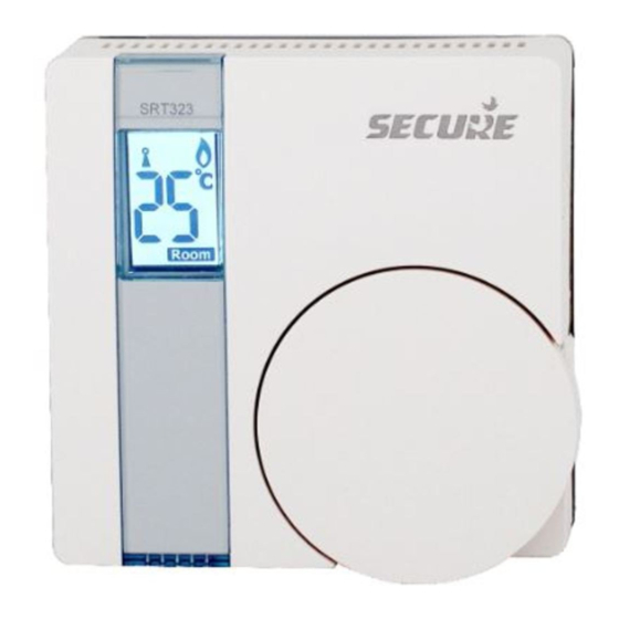
- Page 1 SRT323 User and Installation Instructions Electronic Room Thermostat & Temperature Sensor (Tx) - Z-Wave...
- Page 2 The SRT323 will only operate when 2 x AAA batteries have been fitted. This document provides information specific to the Z- wave technology implemented on SRT323, to ensure interoperability with third party devices.
- Page 3 USER INSTRUCTIONS The Secure SRT323 thermostat uses the latest control technology to provide extremely accurate temperature control which will help to keep your energy usage as low as possible without affecting your comfort levels. In fact comfort levels may well be improved as the control accuracy should ensure that the room does not ‘overheat’...
- Page 4 The thermostat may be operated as an ordinary wired thermostat with no radio connection necessary. In this condition no radio wave symbol is displayed. In the following description, it is assumed that the thermostat has been incorporated into a Z-Wave system. When the thermostat is in the ‘call for heat’...
- Page 5 SRT323 thermostat indicates that it is wirelessly communicating with the rest of the system. If the SRT323 is connected to a wider wireless system, a flashing radio wave would indicate a loss of communication. This may be temporary and can often...
- Page 6 Battery Replacement The SRT323 runs on 2 x type AAA (alkaline) non rechargeable batteries and is designed to give a battery life of approximately two years – under normal usage conditions. Battery should When the batteries are be changed nearing the end of their life...
- Page 7 Remove the old batteries and replace them with two new AAA size alkaline batteries ensuring that they are fitted correctly as indicated by the terminal markings in the battery compartments. Once the batteries are fitted, re-fit the thermostat to the wall plate by engaging with the lugs at the top of the wall plate and push the thermostat into position.
- Page 8 INSTALLER INSTRUCTIONS DIL switch settings On the rear of the unit in the center there are DIL switches that control TPI and installation mode as described below TPI temperature control software Thermostats, using TPI (Time Proportional Integral) control algorithms, will reduce the temperature swing that normally occurs when using traditional bellows or thermally operated thermostats.
- Page 9 Please refer to the 3rd party manufacturers instructions of the Z-Wave controller or gateway that will be used in conjunction with the SRT323 to determine how to add the SRT323 to that controller/gateway. Set DIL switch 1 to ’ON’ position on the back of the unit, scroll through the function menu by rotating the dial.
- Page 10 Mode Z-Wave Function Indication Transmit Node Information Frame (NIF) Learn Mode - use this command for: 1, 3 Include to or exclude from a controller (see page 11) Receive Period Enabled (Listening) This function will keep the unit awake for 60sec to receive commands, no pass or fail response will be provided...
- Page 11 SRT 323. 2 If an outcome is not received within 5sec the SRT323 will report a failure. 3 All association settings will be lost if learn mode has been activated with another controller regardless of a pass or fail result;...
- Page 12 Avoid installing the thermostat against or behind any large metal surfaces which could interfere with the radio signals. The SRT323 should be mounted on an internal wall approximately 1.5 metres from floor level using the wall plate provided and should be in a position away from draughts, direct heat and sunlight.
- Page 13 Fitting the Wall Plate Offer the plate to the wall in the position where the SRT323 is to be mounted and mark the fixing positions through the slots in the wall plate. Drill and plug the wall, then secure the plate into position. The slots in the wall plate will compensate for any misalignment of the fixings.
- Page 14 Wiring Guide SRT323 Thermostat – Internal Wiring Diagram The S RT323 is double insulated and does not require an earth connection, an earth connection block is provided on the wall plate for terminating any cable earth conductors. Earth continuity must be maintained and all bare earth conductors must be sleeved.
- Page 15 Typical combination boiler installation for boiler with built in timer and external room ‘stat SRT323 terminal connections MAINS SUPPLY REMOVE LINK IF FITTED COMBINATION BOILER TERMINALS This diagram is schematic and should be used for guidance only.
- Page 16 Typical combination boiler installation with Secure SHP011 time switch and SRT323 room thermostat SHP011 TERMINALS TERMINALS L-5 SHOULD NOT BE LINKED MAINS SUPPLY SRT323 ROOM For precise terminal connection information STAT please refer to boiler manufacturer’s instructions REMOVE LINK IF...
- Page 17 Fully Pumped Heating System using SRT323 room stat, cylinder stat and Three Port Mid Position Valve with a Secure SHP021/SHP027 electronic programmer. SRT323 ROOM MAINS STAT SUPPLY FROST STAT IF STAT FITTED MRG POSITION VALVE PUMP & BOILER This diagram is schematic and should be used for...
- Page 18 Fully Pumped Heating System using SRT323 room stat, cylinder stat and Two (2 Port) Spring Return Valves with auxiliary switches and a Secure SHP021 / SHP027 electronic programmer. SRT323 ROOM MAINS STAT SUPPLY FROST STAT IF STAT FITTED ZONE ZONE...
- Page 19 Command Class Version Command Class Provides the version number of the Software Multi Level Sensor The SRT323 will respond to the Multilevel Sensor Command Class GET command with a Multilevel Sensor REPORT. This report can be requested or sent unsolicited to the nodes in Group 5.
- Page 20 The Setpoint type of 'Heating' is supported. Command Class The SRT323 will accept Setpoint SET commands only if the Setpoint type is 'Heating'. SRT323 will send a Setpoint REPORT in response to a Setpoint GET message or unsolicited messages can be sent to nodes in Group 4 when the set temperature is changed locally on the SRT323.
- Page 21 Group 2 - Nodes to receive Thermostat Operating State reports. Group 3 - Nodes to receive unsolicited Low Battery Warnings. Group 4 - Nodes to receive unsolicited Thermostat Set Point Reports. Group 5 - Nodes to receive unsolicited Multilevel Sensor Reports. Group 1 contains a maximum of 1 node.
- Page 22 Wake up Interval: 15 Minutes (min) Ÿ Temperature Report: Δ0.5°C (min) and/or Wake up (15 Mins) Ÿ Thermostat specifications SRT323 Electrical Purpose of Control Electronic Room Thermostat + RF (Independently Mounted) 3(1)A 230V AC...
- Page 23 Mechanical Dimensions 86mm x 86mm x 36.25mm Case Material Thermoplastic, flame retardant Ball Pressure Test Temperature 75°C Mounting Wallplate Environmental Cat II 2500V Impulse Voltage Rating IP30 Enclosure Protection Degree 2 Pollution Degree Operating Temperature Range 0°C to +40°C Compliance EN 60730-2-9 Design Standards R&TTE...
- Page 24 European Sales Office CEWE Instrument AB Box 1006, 611 31 Nyköping t: +46 8 600 80 60 e: info@securetogether.eu www.securetogether.eu European Head Office Secure Controls (UK) Ltd. Roman Farm Road Bristol, BS4 1UP Leaflet Number BGX501-877 Issue 1...
Need help?
Do you have a question about the SRT323 and is the answer not in the manual?
Questions and answers