Table of Contents
Advertisement
Quick Links
Advertisement
Table of Contents

Subscribe to Our Youtube Channel
Related Manuals for Secure C1727


Summary of Contents for Secure C1727
- Page 1 Smart Programmable Thermostat C1727 Installation and commissioning guide...
- Page 2 System functionality information, illustrations and product aesthetics published in the document may vary from those of your The Secure Controls products requires electrical connections at mains voltage and should be installed by a suitably competent person, in accordance with Part P of the Building Regulations, BS 7671:2008, (e.g.
- Page 3 In the box Pre-paired Programmable Thermostat Receiver C1727 Display PTD Optional (To be purchased separately) Extra PTD Temperature Sensor THS WiFi Extender HC2.4 (Additional PTD (Additional temperature sensor (Add-on WiFi adapter) for extra zones) for extra zones)
- Page 4 Know your products Receiver C1727 Mains-powered device, compatible with Combination, System and Regular boilers Ÿ (Heat+hotwater+zones) Communicates wirelessly with PTD, temperature sensor and mobile app Ÿ Variant with WiFi module available for remote access Ÿ Simple installation for retrofits with minimum wiring changes required Ÿ...
-
Page 5: What Is Covered
What is covered? How to Install Setup system using PTD Test Receiver C1727 Establish communication Programmable Thermostat Display PTD User mobile app... - Page 6 Compatibility The C1727 Smart Programmer is compatible with most heating control systems and is ideal for S and Y plan system boilers using spring return valves. It works well with compatible combination or system boilers as well as heat pumps requiring On/O control.
- Page 7 Prerequisites For installation For commissioning Tools / things you may need: To commission your system, you need: Secure Controls PTD Flat head Philips head Drill machine screw driver screw driver (2.5 mm drill bit) Smartphone Wire stripper Plier Hammer Version 11.0 and above Marshmallow (version 6.0)
- Page 8 Typical system deployments Single zone heating and hot water * All graphics are for illustration purpose only Internet WiFi C1727 Wireless connection Wired connection Pipes Channel 1 Zone 1 Boiler Hot water Auto by-pass (Two port zone valve) Channel 2...
- Page 9 Typical system deployments Combi-boiler with 1 zone heating * All graphics are for illustration purpose only Internet WiFi C1727 Channel 2 Combi-boiler heating Zone 1 Auto by-pass Valve...
- Page 10 Typical system deployments Combi-boiler with 2 zone heating * All graphics are for illustration purpose only Internet WiFi C1727 Zone 1 Channel 2 Combi-boiler heating Zone 2 Channel 1 Auto by-pass Two port Valve zone valve...
-
Page 11: Product Dimensions
Product dimensions 32.5 mm 153 mm Receiver C1727 100 mm 29.5 mm Programmable Thermostat Display PTD... - Page 12 Download the installer mobile app If you are replacing an existing programmer or time switch or even performing a fresh installation, we recommend that you install the Secure Installer Guide mobile app. 1. Download the Secure installer guide mobile app 2.
-
Page 13: Install The Receiver
Install the receiver Fascia plate Mark out the position... - Page 14 Drill the holes and secure the mounting plate M3.5, AB type screws...
- Page 15 In case of surface wiring (Optional) Break the surface wiring knockout provided on the receiver before proceeding further. Note : Perform this step only if you have surface wiring.
- Page 16 Hot water ON (NO), channel 1 On 2 Heating ON (NO), channel 2 Earth Earth Note: NC - Normally Closed, NO - Normally Open Backplate If replacing, take a picture of your old thermostat connections, label and re-wire as shown in Secure Controls installer app.
-
Page 17: Make Connections
Make connections This diagram is schematic and should be used for guidance only. 230 V Combi-boiler connection Receiver back plate *Note : The receiver has voltage free contacts. A link between terminal L and terminal 2 is required for mains voltage applications. Combi-boiler N - Neutral, L - Live, SL - Switched Live... - Page 18 Make connections This diagram is schematic and should be used for guidance only. 2x heating zone system 1.0/1.5 mm Torque <0.5 Nm *Note : The receiver has voltage free contacts. A link between terminal L and terminal 2 is required for mains voltage applications Note: Connections shown for mains operated 2x heating zone system.
- Page 19 Make connections This diagram is schematic and should be used for guidance only. 1x heating + 1x water heating system 1.0/1.5 mm Torque <0.5 Nm Note: Connections shown for 1x heating and 1x water heating. Connections may vary for di erent boiler types.
- Page 20 Make connections This diagram is schematic and should be used for guidance only. Receiver back plate 3 Port Valve or Y Plan *Note : The receiver has voltage free contacts. A link between terminal L and terminal 2 is required for mains voltage applications Frost Room...
- Page 21 Plug in the WiFi extender HC2.4 (optional) Remove dummy cover Plug in the WiFi adapter Note : WiFi adapter once installed cannot be removed...
- Page 22 Fit the receiver...
-
Page 23: Verify Installation
Verify installation Ch 1 Ch 2 Channel LEDs * Note: LED states 1. Use the top button or bottom button to select the required channel. Default state Solid white 2. Long press any button to initiate setup. It suggests that the receiver During setup Blinking white is ready to be paired with mobile... - Page 24 Install the PTD Ideal mounting location The PTD should be placed approximately 1.5 metres above floor level, in 'free space', away from draughts and sources of heat or electrical interference.
- Page 25 Mark out the mounting position Press The product is shipped in deep sleep mode to save battery. To wake up the device, you must press the button at the rear before setup. Unbox...
- Page 26 Fit the PTD M3.5, AB type screws Click...
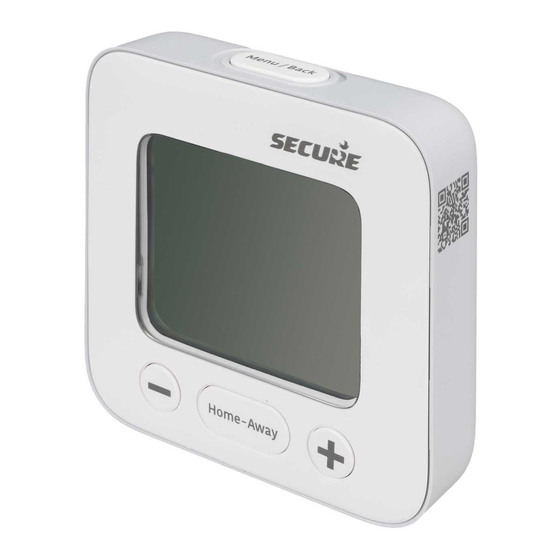
- Page 27 PTD button functions Buttons Functions Menu/Back button Menu/Back Press 1. To enter the main menu button 2. To return to the previous menu / selection Home-Away Press 1. To navigate between modes button (Home/Away) 2. To enter a menu/screen 3. To confirm a change or setting or enter + or - button Press (+)
- Page 28 Establish communication with the receiver Long press the Menu button to establish communication between Receiver C1727 and PTD Long press Menu button Home-Away Notes: The PTD has great temperature sensitivity and you may observe a sudden rise in ambient temperature during the commissioning process triggered by the touch of your...
- Page 29 Establish communication with the receiver Press + or - to select (Yes Press + or - to select fuel or No). Press Home-Away type. Press Home-Away to to confirm selection confirm selection...
- Page 30 Communication established Home-Away PTD after establishing communication with the receiver Note: To add additional PTD or temperature sensor, refer their respective installation guides.
- Page 31 Install the user mobile app 1. Download the Secure Controls user mobile app 2. Open the app and create an account to sign in...
-
Page 32: Product Technical Specifications
Product technical specifications Receiver C1727 Operating temperature 0°C to 40°C Pollution degree Ingress protection IP30 Rated input voltage 230V ± 10% AC Relay contact voltage rating, Volt free (max 230/240 V AC) Ch1 and Ch2 Relay current rating 3(1) A maximum Storage temp. - Page 33 Product technical specifications Programmable Thermostat Display PTD Operating temperature 0°C to 40°C Storage temp. range -20°C to +70°C Relative humidity 0% to 95% non condensing Pollution degree Ingress protection IP30 Non replaceable 2x A Lithium-ion, Battery specifications 3.6 V, 3600 mAh (each) Battery life ≈12 years Wireless communication...
-
Page 34: Products Variants
Product name Model number Battery operated device for zone heating Programmable Thermostat SCD100-000 and hot water Display PTD Mains powered 2 channel receiver C1727 Programmable Thermostat and Programmable Thermostat Display SCT200-000 C1727 (PTD) Mains powered 4 channel receiver H3747 Programmable Thermostat... -
Page 35: Learn More
It lets you establish communication between the boiler/heating system and the PTD to enable the right comfort levels in each of your zones. C1727 is Ideal for replacing traditional wired controls for systems that require separate control of heating and hot water or multiple heating zones. Once commissioned, the Receiver 1. - Page 36 Secure Meters (UK) Ltd South Bristol Business Park, Roman Farm Road, Bristol, BS4 1UP United Kingdom Bristol Phone: +44 117 9788 700 UK Free Phone : 08081687224 UK Direct : +44 196 2826 225 support@securemeters.com Copyright © 2020, SIHPL...
Need help?
Do you have a question about the C1727 and is the answer not in the manual?
Questions and answers
My thermostat won't change temperature it's stuck saying the current temp is 22.4
The Secure C1727 thermostat may be stuck on 22.4 degrees because the "Hold" feature is active. When in Hold mode, all programmed schedules are suspended, and the thermostat maintains the set temperature until the hold is released. To change the temperature, you must cancel the Hold mode by:
1. Pressing the Menu button.
2. Pressing the Home/Away button to enter Hold settings.
3. Pressing the same button again to cancel the Hold.
4. Pressing the Back button to return to the main screen.
Alternatively, on the C1727, you can cancel Hold quickly by pressing the Channel 2 button.
This answer is automatically generated