Table of Contents
Advertisement
Quick Links
POWERNAIL
CO.
®
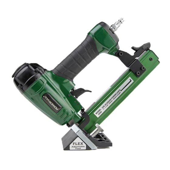
Model 2000 Pneumatic Powernailer™
OPERATION AND MAINTENANCE MANUAL
MANUAL DE OPERACION Y DE MANTENIMIENTO
MANUEL D'INSTRUCTIONS ET D'ENTRETIEN
WARNING
Read this manual before you use this Powernailer®. Follow all safety warnings and
instructions. If you are uncertain about the operation of the nailer, call us directly
at 1-800-323-1653 for assistance or contact the closest Powernail Dealer for help.
Please retain this information for future reference.
REV 13.04.25
Advertisement
Table of Contents

Related Manuals for Powernail 2000 Pneumatic Powernailer


Summary of Contents for Powernail 2000 Pneumatic Powernailer
- Page 1 Read this manual before you use this Powernailer®. Follow all safety warnings and instructions. If you are uncertain about the operation of the nailer, call us directly at 1-800-323-1653 for assistance or contact the closest Powernail Dealer for help. Please retain this information for future reference.
-
Page 2: Table Of Contents
POWERNAIL Model 2000 POWERNAILER purchased from an authorized POWERNAIL distributor, that each serialized manufactured Model 2000 POWERNAILER by POWERNAIL®, for a period of 12 months from the date of purchase; shall be free of defects in materials and workmanship and will meet POWERNAIL’S specifications in effect at the time of product shipment. -
Page 3: Safety Instructions
Powernail Dealer for the correct Powercleats for the Model 2000. Use only Powernail replacement parts in the repair or maintenance of this nailer. Parts or repair services are available from the manufacturer or from agents authorized by the manufacturer. Repairs should be carried out only by trained service personel in the field of fastener driving tools who will observe proper safety controls while performing maintenance. -
Page 4: Operating The Tool
OPERATION The Model 2000 nails down flooring from The Model 2000 5/16” to 9/16” using the Powernail FLEX installs tongue and adjustable foot assembly that can be adjusted to groove flooring fit different flooring profiles. from To use the Model 2000, simply snug up the 5/16”... -
Page 5: Air Supply
OPERATION, continued... Figure 1. FOOT ADJUSTMENT / NAIL LOCATION Loosen both adjusting knobs Adjust the foot to a sample of your wood. (#76, See Figure 1.) Hold nailer on a piece of sample flooring 76. Adjusting Knobs (2) to be installed. Adjust the foot rest (#74) so it lays flat on the finished surface of the flooring (Figure 1). - Page 6 OPERATION, continued... LOADING THE FASTENERS Figure 3. 1. Depress the LOCK (61) to release the MOVABLE CHANNEL GUIDE (44) and slide the channel guide out fully as shown in Figure 3. 2. Place a full stick of 1” or 1-1/4” 20 gage Powercleats into the FIXED CHANNEL (43).
-
Page 7: Safety Labels
MAINTENANCE REGULAR MAINTENANCE 1. Frequent, but not excessive, lubrication is required for best performance. Oil added through the airline connection will lubricate internal parts. An automatic airline oilier is recommended but oil may be added manually before every operation or after about 1 hour of continuous use. Only a few drops of oil at a time are necessary. -
Page 8: Clearing A Jam
CLEARING A JAM Disassembly: (See Figure 5.) 1) NOTE: Do not remove the two M5 screws (80). 2) Remove the two adjusting knobs (76) and cap screws (77). 3) Remove the support shoe (73) and foot rest (74). 4) Remove three M4 screws (78) with a 3mm allen wrench and lift off foot (71). 5) Slide the safety arm (75) to the side. -
Page 9: Troubleshooting Chart
TROUBLE SHOOTING CHART Here are some common issues that may occur during use. If the nailer is not working as it should, stop using the tool immediately and resolve the issue before continuing. PROBLEM POSSIBLE CAUSE SOLUTION 1. O-ring (31) in trigger valve is damaged. 1. -
Page 10: Schematic / Parts List
MODEL 2000 PARTS LIST ITEM DESCRIPTION Avail. PART # ITEM DESCRIPTION Avail. PART # SCREW M4 x 10mm TRIGGER PIN BUSHING SCREW M4 x 16mm EXHAUST COVER WASHER WASHER .125 DIA x .312 ROLL PIN 09-20FN2042 SCREW M5 x 20mm CHANNEL 09-20FN2043 SPRING WASHER 5... - Page 11 MODEL 2000 SCHEMATIC...
-
Page 12: Nail Depth Chart
This is only a guide. Results should be tested in the field before proceeding. Nail Penetration for 3/4" Subflooring. 1-1/4” 20 GAGE POWERCLEATS® 1” 20 GAGE POWERCLEATS® ©Powernail Company 2013 POWERNAIL COMPANY, INC. 1300 Rose Road, Lake Zurich, IL 60047 US Phone: 1-800-323-1653 or 847-847-3000 www.powernail.com...
Need help?
Do you have a question about the 2000 Pneumatic Powernailer and is the answer not in the manual?
Questions and answers