REMEHA Gas 310 ECO Technical Information
High efficiency condensing
boiler with low nox emission
Hide thumbs
Also See for Gas 310 ECO:
- Technical information (59 pages) ,
- User manual lines (20 pages) ,
- Assembly instructions manual (8 pages)

Related Manuals for REMEHA Gas 310 ECO


Summary of Contents for REMEHA Gas 310 ECO
-
Page 1: Technical Information
Technical information Remeha Gas 310 ECO High efficiency condensing boiler with low NO emission Heat outputs: 51 - 573 kW 62560.indd 1 62560.indd 1 18-6-2009 13:14:32 18-6-2009 13:14:32... -
Page 2: Table Of Contents
Remeha Gas 310 ECO TABLE OF CONTENTS Preface 8.2.6 Low water level protection (flow and content) SAFETY instructions 8.2.7 High limit protection 1.1 Symbols 8.2.8 Air pressure differential sensor (LDS) General description of boiler 8.3 Connections 8.4 Wiring diagram DESIGN 8.5 Switch sequence diagram... - Page 3 12 Operating mode 15.4.7 Cleaning the condensate collector 48 12.1 Operating mode (x[[) 15.4.8 Cleaning the syphon 12.2 Read-out mode (X [[) 15.4.9 Cleaning/Replacing the Ignition 12.3 Control strategy c Ionisation electrode 12.4 Shut-off (b xx) 15.4.10 Gas filter check 12.4.1 Shut-off 15.4.11 Cleaning the inspection glass 12.4.2 Shut-off mode...
-
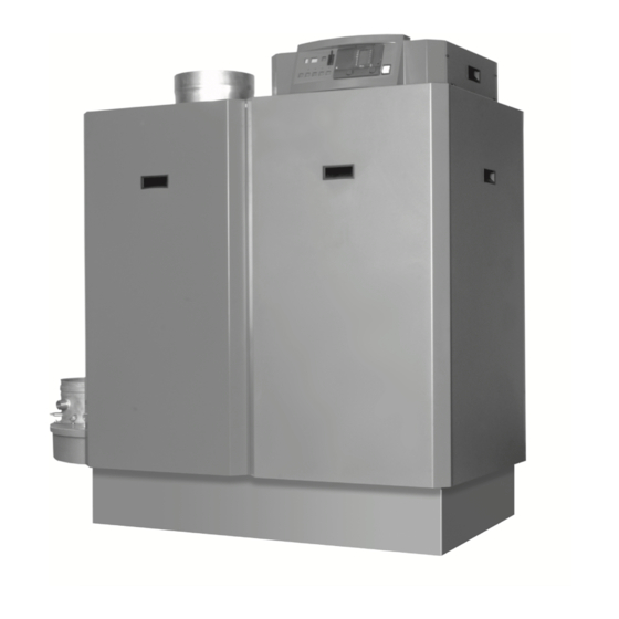
Page 4: Preface
Broag Ltd. for record purposes. fig. 01 Artist impression Gas 310 ECO 3D.AL.31H.000.S.01 62560.indd 4 62560.indd 4 18-6-2009 13:14:51... -
Page 5: Safety Instructions
Read and familiarise yourself with these instruc- tions. Boiler modifications and spare parts The boiler must not be modified or non-Remeha spare General Instructions parts fitted without the express written approval of Keep unauthorised personnel away from the boiler. Do Remeha. -
Page 6: General Description Of Boiler
- Gas Appliances Directive, no. 90/ 396/ EEC purposes. The Gas 310 ECO frame is fitted with a set - Efficiency Directive, no. 92/ 42/ EEC of casters to enable the assembled unit to be easily - EMC Directive, no. -
Page 7: Design
DESIGN 3.1 Boiler version fig. 02 Cross-section Remeha Gas 310 ECO (Left hand boiler illustrated) 00.31H.79.00002 Adapter ø 200/ ø 250 (optional) The service side of the boiler (with the heat exchanger inspection cover) is the front. Air supply grille... -
Page 8: Operating Principle
Remeha Gas 310 ECO 3.2 Operating principle Combustion air is drawn into the inlet connection from the plant room (room ventilated version) or from outside via the eccentric flue system (room sealed) by an air supply fan. On the inlet side of the fan is a specially designed... -
Page 9: Technical Data
TECHNICAL DATA 4.1 Dimensions fig. 03 Elevation drawings (left-hand version shown) 04.31H.79.00002 É Flow connection NW 80, DIN 2576 Ê Return connection NW 65, DIN 2576 Ï Gas connection 2” BSP (F) Ò Condensate drain 1 ¼” nb plastic waste Ñ... - Page 10 Remeha Gas 310 ECO 4.2 Technical data Remeha Gas 310 ECO Boiler type Unit 5 sections 6 sections 7 sections 8 sections 9 sections General Boiler control options Modulating, high/ low or on/ off Nominal output Pn (80/ 60°) max kW Nominal output Pn (50/ 30°)
-
Page 11: Quotation Specification
(average) Colour of casing 2002 (red); 9023 (grey) table 02 Technical data Remeha Gas 310 ECO 4.3 Quotation specification - Cast aluminium - sectional pre-mix gas fired fully condensing, modulating floor standing boiler - Rigid steel box frame... -
Page 12: Efficiency Information
Up to 106.4% at Hi (98% at Hs) at an average water temperature of 40° (50/ 30°). APPLICATION DATA The Gas 310 ECO can be used on all new and refur- the boiler/s controls to make full use of their fully modu- bishment projects in both single and multiple configu- lating features, ensuring that the boiler closely matches rations. -
Page 13: Installation Instructions For Heating Installer
WARNING! Use retaining straps to control The Remeha Gas 310 ECO is a CE certified boiler and the rate of travel - Do not stand in front of the boiler! must not be modified or installed in any way contrary to - Manoeuvre the boiler to required final position. -
Page 14: Flue Gas Discharge And Air Supply
7.3.1 General the boiler and at least 300 mm on both ends (800 mm The Remeha Gas 310 ECO is suitable for both conven- if the instrument panel is rotated to face the short end). tional room ventilated or eccentric room sealed opera- An isolating gas main cock must be installed near the tion. -
Page 15: Connection Options
310 ECO can be found in section 7.3.7. 7.3.3 Connection options The Remeha Gas 310 ECO is available in a room venti- lated and a room sealed version. If the room-sealed ver- sion is used, the grille must be removed before installing the air supply pipe. -
Page 16: Single Boiler, Room Sealed Flue
* When flue gas discharge pipes with a diameter of 200 table 05 Calculation data room sealed applications mm are used, an optional adapter is required for con- nection to the Remeha Gas 310 ECO from ø 250 - ø Example: 200 mm. - Page 17 Exc. fig. 09 Vertical terminal for room sealed operation Number of øD ød1 ød2 øD3 ext. øD4 int. sections 2350 2500 2350 2500 2350 2500 2350 2500 2350 2500 table 06 Dimensions vertical terminal in mm 62560.indd 17 62560.indd 17 18-6-2009 13:14:54 18-6-2009 13:14:54...
-
Page 18: Different Pressure Zones
Pressurised installations with a boiler/ system content 00.31H.79.00012 ratio of 1:10 or less should not require water treatment, The Remeha Gas 310 ECO boilers are capable of oper- provided that the following conditions apply: ating with the air inlet and flue outlet in different pres- sure zones (CLV System). -
Page 19: Safety Valve
A safety valve should be fitted in accordance with BS New systems should be flushed thoroughly to remove all 6644. The flow pipe on the Remeha Gas 310 ECO traces of flux, debris, grease and metal swarf generated includes a fitting, which can be used for a safety valve;... - Page 20 Remeha Gas 310 ECO OpenTherm or rematic modulating cascade ® controller boiler pump safety valve non return valve isolating valve automatic air vent low loss header drain cock 10. system pump 11. expansion vessel system 12. flow temperature sensor 13. outside temperature sensor fig.
- Page 21 The minimal dimensions of low loss header and various pipes, based on a dT of 11° are represented in table The low loss header has to be sized for the maximal flow Q required. The Remeha Gas 310 ECO has no built-in pump. Output Flow Q D ø...
-
Page 22: Installation Instructions For Electrical Installer
INSTALLATION INSTRUCTIONS FOR ELECTRICAL INSTALLER 8.1 General 8.2.3 Power consumption The Remeha Gas 310 ECO is supplied as standard with Power consumption at stand-by /part load /full load: electronic operating and flame ionisation safety controls - 5 sections: 12 Watt / 53 Watt / 303 Watt... -
Page 23: Temperature Control
Once started the LDS function is switched off for modu- lation purposes. 8.2.6 Low water level protection (flow and content) The Remeha Gas 310 ECO is equipped with low water 8.3 Connections protection based on temperature differences (dT) The terminal strips and boiler connectors can be seen between flow and return. -
Page 24: Wiring Diagram
Remeha Gas 310 ECO 8.4 Wiring diagram fig. 18 Wiring diagram 04.31H.SC.00001 62560.indd 24 62560.indd 24 18-6-2009 13:14:57 18-6-2009 13:14:57... -
Page 25: Switch Sequence Diagram
Switch sequence diagram 04.31H.79.00003 8.6 Boiler control 8.6.1 Introduction The Remeha Gas 310 ECO can be controlled using one of the following methods: Note: when using on/off control the boiler will also modulate to maintain the flow temp set point (param-... -
Page 26: Modulating Controls General
Remeha Gas 310 ECO 8.6.2 Modulating controls general (two wire control) To make full use of the boiler’s modulating feature, an OpenTherm or a rematic control can be connected. ® ® These controls will provide optimised time and weather compensation to achieve maximum efficiency and mini- mum boiler cycling whilst maintaining design condition within the building. -
Page 27: High/ Low Control (2 X No Volt Switched Pairs)
Output 8.6.5 High/ low control (2 x no volt switched pairs) Description signal The heat output is controlled between part load (50%, adjustable) and full load, by means of a two-stage con- 0 volts Boiler off troller, terminal connections X29-9 and X29-10 low fire; 0.5 volts Alarm signal/lock-out X29-7 and X29-8 high fire. -
Page 28: Options/ Accessories
8.9.1 Boiler or System pump control vated (parameter J). The Remeha Gas 310 ECO has a facility to provide a power supply (230V Max 2 amps) to run or control an 8.8.2 Gas valve leak proving system VPS external boiler or system pump. -
Page 29: Installation Instructions For Gas Installer
INSTALLATION INSTRUCTIONS FOR GAS INSTALLER 9.1 Gas connection Gas/ air ratio control The Gas 310 is suitable for use with natural gas only. The boiler has a pressure differential gas/ air ratio The gas connection is at the top of the boiler (see fig. control. - Page 30 Remeha Gas 310 ECO When full load is reached, measure dP gas at 17.c measuring point P on the underside of the gas valve multiblock and at the measuring point PL on the venturi and compare to the value in table 11.
-
Page 31: Shutdown
Note: 2. Close the gas cock. The Remeha Gas 210 ECO is supplied with a number Important!! of factory default settings that should be correct for most When the boiler is out of opera- installations. -
Page 32: Control And Safety Equipment
Remeha Gas 310 ECO CONTROL AND SAFETY EQUIPMENT 11.1 General 11.1.1 Instrument panel layout The boiler is supplied with a standard set of defaults The instrument panel consists of (see fig. 25): pre-programmed for normal operation but can be tai- Operation switch lored by the Engineer to suit most site conditions. -
Page 33: Led Indicators
11.1.2 LED indicators Following a manual override the boiler will return to nor- The instrument panel has 4 indicating LED’s with the fol- mal (auto control) if no keys are used within a 15-minute lowing functions: period. - The LED above the [-] key (in the h symbol); when 11.2.3 Forced mode ‘low’... - Page 34 Remeha Gas 310 ECO OPERATING MODE 12.1 Operating mode (x [[) During normal operation the code-display shows the sta- tus (position in cycle) of the boiler, with the t -display indicating the actual flow temperature. The digits or letters in the code-display have the following...
- Page 35 Requested (and permitted by boiler control) 00 - )0 (=100%) output (%) is displayed, irrespective of boiler demanded value control setting. Calculated output (%) 10 - )0 (=100) (actual value) Analog input voltage (volts) 00 - )0 (=100) ((actual value) Control strategy (see section 12.3) 01 - 06 Current water pressure...
- Page 36 Remeha Gas 310 ECO Code Description Shut-off code (see table 23) Operating code, at shut-off intervention (section 12.1) Flow temperature, at shut-off intervention Return temperature, at shut-off intervention Flue gas temperature, at shut-off intervention Boiler block temperature, at shut-off intervention...
-
Page 37: Setting Mode
SETTING MODE 13.1 User level setting mode (X [[) Setting mode is used to change various settings to suit individual requirements. The required code is selected by pressing the m key until ! appears in the code win- dow. Select the required code with the s key. Now press the [+] key to increase a setting or the [-] key to decrease a setting. -
Page 38: Pump Run On Time (@)
Remeha Gas 310 ECO 13.1.2 Pump run on time (@) 13.2 Setting mode service level (only for the quali- Pump run on time can be adjusted (Please refer to fied service engineer) (X [[) installation contractor). To prevent accidental, unauthorised access by non-qual-... - Page 39 Important!! when the boiler is running at ‘low’. Only make changes after con- The percentage ‘high’ position depends on the set maxi- sulting Remeha sales support department. mum central heating speed. Important!! Only make changes after con- sulting Remeha sales support department.
-
Page 40: Forced Part Load Time (*)
Remeha Gas 310 ECO 13.2.3 Forced part load time (*) 13.2.6 Switch point high/low operation signal (C) Parameter Adjustable between 0 and 300 seconds. Parameter C, adjustable between 0 and 60 (x 100) The boiler always starts with a specified output for a rpm. -
Page 41: Minimum Water Pressure (I)
13.2.12 Minimum water pressure (I) Parameter I, adjustable between 0 and 6 bar. This setting only applies if an optional hydraulic pres- sure sensor has been connected. This value sets the point at which the boiler will shut- down if the system pressure falls below it. The boiler will resume normal operation when pressure is restored. -
Page 42: Fault-Finding
Remeha Gas 310 ECO FAULT-FINDING 11 Operating hours (hundred thousands 14.1 General and ten thousands) If the boiler does not start up, check the following: 80 Operating hours (thousands and hun- - Is a 230 V supply present; dreds) - Is there a heat demand;... - Page 43 Failure Description Cause/check points Flame simulation, (flame detect- - Burner glows as a result of a high CO percentage. ed when control is in the off - Check the combined ignition/ionisation electrode (gap should be 3 to position) 4 mm apart). - Gas valve multiblock is leaking or is stuck in the open position.
- Page 44 Remeha Gas 310 ECO Locked input open - Maximum thermostat (= external protection), connected to terminals X29-1 and X29-2 on the terminal strip, has tripped or wire bridge has been removed - Fuse F3 on automatic burner unit is defective.
- Page 45 Boiler block temperature too Check: high - The heating pump is running - There is sufficient water flow through the boiler - The water pressure is > 0.8 bar. Gas leak VA1 (optional) The VPS gas leakage control unit has detected a leak. Check for exter- nal leaks, otherwise replace gas valve multiblock.
-
Page 46: Inspection And Maintenance Instructions
Gas 310 ECO INSPECTION AND MAINTENANCE INSTRUCTIONS 15.1 General - Check ignition probe earth. The Remeha Gas 310 ECO has been designed to need - Check condition of ignition/ ionisation probe replace if minimum maintenance, but to ensure optimum efficiency necessary. -
Page 47: Inspection Of Air Box And Dirt Trap
15.4.1 Inspection of air box and dirt trap 15.4.4 Cleaning the fan The air box has a dirt trap on the inlet side. Check this Use compressed air or a synthetic brush to clean fan, for dirt, leaves, etc. If the boiler is closed, the clamp- be careful not to disturb the balance clips on the ing strip under the casing must be removed first, check vanes... -
Page 48: Cleaning The Burner Assembly
Remeha Gas 310 ECO 15.4.6 Cleaning the burner assembly Clean the burner assembly by using compressed air only - between 2 and 5 bar with the nozzle positioned a min of 10mm away and towards the face of the burner. - Page 49 15.4.10 Gas filter check Re-assemble boiler in reverse order, check front plate Measure pressure differential dP at measuring points P gasket and insulation piece, replace if required. Also and P (see fig. 37) on the gas filter. check the gasket on fan and on gas valve, replace if - If the dP value is above 10 mbar: gas filter must be necessary.
- Page 50 Remeha Gas 310 ECO 15.5 Exploded view and spare parts list GAS310/08-04 fig. 39 Exploded view 62560.indd 50 62560.indd 50 18-6-2009 13:15:01 18-6-2009 13:15:01...
- Page 51 Pos. nr. Part description Pos. nr. Part description Teflon tape O-ring Ø 183 Loctite Fan (for 7, 8, 9 sections) PVC glue Nut M8 Cleaning tool Sealing plate fan/ mixing elbow (for 7, 8, 9 sec- tions) Mixing elbow Bolt M8 x 30 Air box Nut M12 Nut M8...
- Page 52 Remeha Gas 310 ECO Pos. nr. Part description Pos. nr. Part description Inspection cover Plug À” Bolt M6 x 16 Sealing cable Ø 10 Return blind pipe Flue gas sensor jacket Second return distribution pipe Straight connecting flange Flue gas sensor...
- Page 53 APPENDICES 16.1 Control menu step through modes with in code- display - display the m - key Operating mode 0 - 9 Flow temperature Shut-off code only digit or letter Forced full load (High) Forced part load (Low) Gas leakage control Burner cooling step within the mode with the s- key Setting mode...
- Page 54 Remeha Gas 310 ECO 16.2 Shut-off codes Code Description Cause/Check )* Insufficient air transport during pre-ventilation. - Air supply or flue gas discharge for The boiler is locked after 5 restarts (6 starts) with code 08 blockages/ installation faults (see section 14.4).
- Page 55 %@ Maximum flue gas temperature has been exceeded. The - The set maximum flue gas tempera- boiler shuts down for 150 seconds, followed by a restart. If the ture flue gas temperature rises 5° above the maximum flue gas - Boiler adjustment temperature, a lockout follows with code 52 (see section - Boiler for fouling.
- Page 56 Broag Ltd. Remeha House Molly Millars Lane RG41 2QP WOKINGHAM, Berks. © Copyright Tel: +44 118 9783434 All technical and technological information contained in these technical instructions, as Fax: +44 118 9786977 well as any drawings and technical descriptions furnisched by us remain our property and Internet: uk.remeha.com...
Need help?
Do you have a question about the Gas 310 ECO and is the answer not in the manual?
Questions and answers