Dell PowerEdge R530 Owner's Manual
Hide thumbs
Also See for PowerEdge R530:
- Getting started (2 pages) ,
- Owner's manual (182 pages) ,
- Getting started (2 pages)
Table of Contents
Advertisement
Quick Links
Download this manual
See also:
Owner's Manual
Advertisement
Table of Contents
Troubleshooting

Related Manuals for Dell PowerEdge R530


Summary of Contents for Dell PowerEdge R530
- Page 1 Dell PowerEdge R530 Owner's Manual Regulatory Model: E29S Series Regulatory Type: E29S001...
- Page 2 WARNING: A WARNING indicates a potential for property damage, personal injury, or death. Copyright © 2014 Dell Inc. All rights reserved. This product is protected by U.S. and international copyright and intellectual property laws. Dell and the Dell logo are trademarks of Dell Inc.
-
Page 3: Table Of Contents
Contents 1 About your system....................8 ..................... 8 Front-panel features and indicators ..........................10 LCD panel features ..........................10 Home screen ............................ 11 Setup menu ............................11 View menu ......................12 Hard-drive indicator patterns ....................13 Back-panel features and indicators ..........................15 NIC indicator codes ..................... - Page 4 ...........................38 About Boot Manager ........................ 38 Entering Boot Manager ......................38 Boot Manager main menu ......................38 About Dell Lifecycle Controller ........................39 Changing the boot order .......................39 Choosing the system boot mode ....................39 Assigning a system and setup password ................ 40 Using your system password to secure your system ............
- Page 5 ................... 63 Installing a 3.5 inch hard-drive blank .......... 64 Removing a 2.5 inch hard drive from a 3.5 inch hard-drive adapter ..........65 Installing a 2.5 inch hard drive into a 3.5 inch hard-drive adapter ............65 Removing a hard-drive adapter from a hard-drive carrier .............
- Page 6 ..................101 Installing the power supply unit blank ................... 101 Removing an AC power supply unit ..................... 102 Installing an AC power supply unit ................103 Non-redundant AC power supply (cabled) .................105 Wiring instructions for a DC power supply unit .....................108 Removing a DC power supply unit ....................109 Installing a DC power supply unit...
- Page 7 Warning messages ........................139 Diagnostic messages ..........................140 Alert messages 6 Using system diagnostics................141 ....................141 Dell Embedded System Diagnostics ..............141 When to use the Embedded System Diagnostics ................141 Running the Embedded System Diagnostics ......................142 System diagnostic controls 7 Jumpers and connectors................
-
Page 8: About Your System
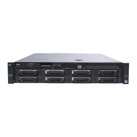
About your system The Dell PowerEdge R530 is a rack server that supports up to two processors based on the Intel E5-2600 v3 product family, up to 12 DIMMs, and up to eight drive bays for hard drives/ SSDs. The PowerEdge R530 system is available in the following configurations: •... - Page 9 Allows you to connect USB devices to the system USB management port/ or provides access to the iDRAC Direct features. iDRAC Direct For more information, see the Integrated Dell Remote Access Controller User’s Guide at dell.com/esmmanuals. The USB management port is USB 2.0-compliant.
-
Page 10: Lcd Panel Features
The system's LCD panel provides system information and status and error messages to indicate if the system is operating correctly or if the system needs attention. For more information on error messages, see the Dell Event and Error Messages Reference Guide at dell.com/esmmanuals. •... -
Page 11: Setup Menu
SEL. This is useful when trying to match an LCD message with an SEL entry. Select Simple to display LCD error messages in a simplified user-friendly description. For more information on error messages, see the Dell Event and Error Messages Reference Guide at dell.com/esmmanuals. Set home Select the default information to be displayed on the LCD Home screen. -
Page 12: Hard-Drive Indicator Patterns
Hard-drive indicator patterns Figure 3. Hard-drive indicators hard-drive activity indicator hard-drive status indicator hard drive NOTE: If the hard drive is in Advanced Host Controller Interface (AHCI) mode, the status indicator (on the right side) does not function and remains OFF. Drive-status indicator Condition pattern (RAID only) -
Page 13: Back-Panel Features And Indicators
Drive-status indicator Condition pattern (RAID only) Blinks green three seconds, Rebuild aborted amber three seconds, and OFF six seconds Back-panel features and indicators Figure 4. Back-panel features and indicators for a non-redundant power supply unit chassis and a redundant power supply unit chassis Item Indicator, button, or Icon... - Page 14 Item Indicator, button, or Icon Description connector Non-Redundant Power 450 W Supply Unit Half Height PCIe Allows you to connect PCIe expansion cards. expansion card slots (5) Integrated 10/100/1000 Mbps NIC connector Ethernet connectors (2) System identification Connects the optional system status indicator connector assembly through the optional cable management arm.
-
Page 15: Nic Indicator Codes
NIC indicator codes Figure 5. NIC indicators link indicator activity indicator Convention Indicator pattern Description Link and activity indicators The NIC is not connected to the network. are OFF Link indicator is green The NIC is connected to a valid network at its maximum port speed (1 Gbps). - Page 16 Do not disconnect the power cord or unplug the PSU when updating firmware. If firmware update is interrupted, the PSUs will not function. You must roll back the power supply firmware by using Life cycle controller. See Dell Lifecycle Controller User’s Guide at dell.com/esmmanuals Flashes green...
- Page 17 Convention Power indicator Condition pattern CAUTION: When correcting a PSU mismatch, replace only the PSU with the flashing indicator. Swapping the opposite power supply unit to make a matched pair can result in an error condition and unexpected system shutdown. To change from a High Output configuration to a Low Output configuration or vice versa, you must power down the system.
-
Page 18: Indicator Codes For Non-Redundant Power Supply
Convention Power indicator Condition pattern Green The handle/LED indicator lights green indicating that a valid power source is connected to the PSU and that the PSU is operational. Flashing green When hot-adding a PSU, the handle of the new power supply unit flashes green five times at 4 Hz rate and turns off. -
Page 19: Documentation Matrix
Install the operating system Operating system documentation at dell.com/ operatingsystemmanuals Get an overview of the Dell Systems Management Dell OpenManage Systems Management Overview offerings Guide at dell.com/openmanagemanuals Configure and log in to iDRAC, set up managed... -
Page 20: Quick Resource Locator (Qrl)
Use the Quick Resource Locator (QRL) to get immediate access to system information and how-to videos. This can be done by visiting www.dell.com/QRL or by using your smartphone or tablet and a model specific Quick Resource (QR) code located on your Dell PowerEdge system. To try out the QR... -
Page 21: Performing Initial System Configuration
Turn the system on by pressing the power button or using iDRAC. Turn on the attached peripherals. Setting up and configuring the iDRAC IP address You can set up the Integrated Dell Remote Access Controller (iDRAC) IP address by using one of the following interfaces: •... -
Page 22: Installing The Operating System
For more information, see the Integrated Dell Remote Access Controller User’s Guide at dell.com/esmmanuals. You can also remotely monitor and manage the server by using the Dell OpenManage Server Administrator (OMSA) software and OpenManage Essentials (OME) systems management console. For more information, see dell.com/openmanagemanuals. - Page 23 Download the drivers you require to a diskette drive, USB drive, CD, or DVD.
-
Page 24: Pre-Operating System Management Applications
Your PowerEdge system has the following pre-operating system management applications: • System Setup • Boot Manager • Dell Lifecycle Controller Navigation keys The navigation keys can help you access the pre-operating system management applications. Description <Page Up> Moves to the previous screen. -
Page 25: Entering System Setup
The iDRAC Settings utility is an interface to set up and configure the iDRAC parameters by using UEFI. You can enable or disable various iDRAC parameters by using the iDRAC Settings utility. For more information about this utility, see the Integrated Dell Remote Access Controller User’s Guide at dell.com/esmmanuals. Device Settings Enables you to configure device settings. -
Page 26: System Information Screen
Menu Item Description Serial Communication Displays options to enable or disable the serial ports and specify related features and options. System Profile Settings Displays options to change the processor power management settings, memory frequency, and so on. System Security Displays options to configure the system security settings like, system password, setup password, TPM security, and so on. -
Page 27: Processor Settings Screen
Menu Item Description Spare with Advanced ECC Mode. By default, the Memory Operating Mode option is set to Optimizer Mode. NOTE: The Memory Operating Mode can have different defaults and available options based on the memory configuration of your system. Node Interleaving Specifies if Non-Uniform Memory architecture (NUMA) is supported. -
Page 28: Sata Settings Screen
Menu Item Description DCU IP Prefetcher Enables or disables the Data Cache Unit (DCU) IP prefetcher. By default, the DCU IP Prefetcher option is set to Enabled. Execute Disable Enables or disables the execute disable memory protection technology. By default, the Execute Disable option is set to Enabled. Logical Processor Idling Enables or disables the operating system capability to put logical processors in the idling state in order to reduce power consumption. - Page 29 Menu Item Description Port A Sets the drive type of the selected device. For Embedded SATA settings in ATA mode, set this field to Auto to enable BIOS support. Set it to OFF to turn off BIOS support. For AHCI mode or RAID mode, BIOS always enables support. Model Displays the drive model of the selected device.
- Page 30 Menu Item Description Capacity Displays the total capacity of the hard drive. The field is undefined for removable media devices such as optical drives. Port F Sets the drive type of the selected device. For Embedded SATA settings in ATA mode, set this field to Auto to enable BIOS support. Set it to OFF to turn off BIOS support.
-
Page 31: Boot Settings Screen
Menu Item Description Drive Type Displays the type of drive attached to the SATA port. Capacity Displays the total capacity of the hard drive. The field is undefined for removable media devices such as optical drives. Boot Settings screen You can use the Boot Settings screen to set the Boot mode to either BIOS or UEFI. It also allows you to specify the boot order. -
Page 32: Integrated Devices Screen Details
Integrated Devices screen details The Integrated Devices screen allows you to view and configure the settings of all integrated devices including the video controller, integrated RAID controller, and the USB ports. In the System Setup Main Menu, click System BIOS → Integrated Devices. Menu Item Description USB 3.0 Setting... -
Page 33: Serial Communication Screen
automatically used as the primary display even if the Embedded Video Controller setting is Disabled. Current State of Embedded Video Controller Displays the current state of the Embedded Video Controller. Current State of Embedded Video Controller is a read only field, indicating the current state for the Embedded Video Controller. -
Page 34: System Profile Settings Screen
You can only change the rest of the options if the mode is set to Custom. By default, the System Profile option is set to Performance Per Watt Optimized (DAPC). DAPC is Dell Active Power Controller. NOTE: The following parameters are available only when the System Profile is set to Custom. -
Page 35: System Security Settings Screen
Menu Item Description Energy Efficient Turbo Enables or disables the Energy Efficient Turbo. Energy Efficient Turbo (EET) is a mode of operation where a processor’s core frequency is adjusted within the turbo range based on workload. Enables or disables the processor to switch to a minimum performance state when it is idle. - Page 36 Menu Item Description Intel AES-NI Improves the speed of applications by performing encryption and decryption using the Advanced Encryption Standard Instruction Set and is set to Enabled by default. System Password Sets the system password. This option is set to Enabled by default and is read-only if the password jumper is not installed in the system.
-
Page 37: Miscellaneous Settings Screen
Menu Item Description Secure Boot Enables Secure Boot, where the BIOS authenticates each pre-boot image using the certificates in the Secure Boot Policy. Secure Boot is disabled by default. Secure Boot Policy When Secure Boot policy is Standard, the BIOS uses the system manufacturer’s key and certificates to authenticate pre-boot images. -
Page 38: About Boot Manager
Launches system utilities menu such as system diagnostics and UEFI shell. About Dell Lifecycle Controller Dell Lifecycle Controller allows you to perform useful tasks such as configuring BIOS and hardware settings, deploying an operating system, updating drivers, changing RAID settings, and saving hardware... -
Page 39: Changing The Boot Order
For more information about Dell Lifecycle Controller, see the documentation at dell.com/ esmmanuals. Changing the boot order You may have to change the boot order if you want to boot from a USB key or an optical drive. The instructions given below may vary if you have selected BIOS for Boot Mode. -
Page 40: Using Your System Password To Secure Your System
About this task To assign a System Password and Setup Password, follow the steps below: Steps To enter System Setup, press <F2> immediately after a power-on or reboot. From the System Setup Main Menu, select System BIOS and press <Enter>. The System BIOS screen is displayed. -
Page 41: Deleting Or Changing An Existing System And/Or Setup Password
NOTE: You can use the Password Status option in conjunction with the System Password and Setup Password options to protect your system from unauthorized changes. Deleting or changing an existing system and/or setup password Prerequisites Ensure that the Password jumper is set to enabled and the Password Status is set to Unlocked before attempting to delete or change the existing System and/or Setup password. -
Page 42: Embedded System Management
NOTE: Accessing some of the features on the iDRAC Settings utility requires the iDRAC Enterprise License upgrade. For more information on using iDRAC, see the iDRAC User's Guide at dell.com/esmmanuals. Entering the iDRAC Settings utility Turn on or restart the managed system. -
Page 43: Installing And Removing System Components
Damage due to servicing that is not authorized by Dell is not covered by your warranty. Read and follow the safety instructions that came with the product. -
Page 44: Recommended Tools
Related Links Installing the system cover Installing the front bezel Recommended tools You need the following tools to perform the removal and installation procedures: • Key to the front bezel lock. This is required only if you have a front bezel. •... -
Page 45: Installing The Front Bezel
Damage due to servicing that is not authorized by Dell is not covered by your warranty. Read and follow the safety instructions that came with the product. -
Page 46: Removing The System Cover
Removing the system cover Prerequisites Ensure that you read the Safety instructions. Follow the procedure listed in Before working inside your system. Steps On top of the system, locate the latch release lock and rotate the lock to the unlocked position. Lift the latch and slide the cover back. -
Page 47: Inside The System
Damage due to servicing that is not authorized by Dell is not covered by your warranty. Read and follow the safety instructions that came with the product. - Page 48 Figure 11. Inside the System—Redundant Power Supply Unit Chassis control-panel board hard-drive backplane cooling fan (5) power-interposer board power supply (redundant) optional expansion-card riser processor (2) DIMM (12)
-
Page 49: Cooling Shroud
Damage due to servicing that is not authorized by Dell is not covered by your warranty. Read and follow the safety instructions that came with the product. - Page 50 Ensure that you read the Safety instructions. Follow the procedure listed in Before working inside your system. If applicable, disconnect the power or data cables from expansion card (s). NOTE: If applicable, close the expansion-card latch on the cooling shroud to release the full- length card.
-
Page 51: Installing The Cooling Shroud
Damage due to servicing that is not authorized by Dell is not covered by your warranty. Read and follow the safety instructions that came with the product. - Page 52 Figure 14. Memory socket locations Memory channels are organized as follows: Processor 1 channel 0: slots A1 and A5 channel 1: slots A2 and A6 channel 2: slots A3 and A7 channel 3: slots A4 and A8 Processor 2 channel 0: slot B1 channel 1: slot B2 channel 2: slot B3...
-
Page 53: General Memory Module Installation Guidelines
channel 3: slot B4 The following table shows the memory populations and operating frequencies for the supported configurations. DIMMs Populated/ Operating Frequency (in DIMM Type Maximum DIMM Rank/Channel Channel MT/s) 1.2 V RDIMM 2133, 1866, 1600, and 1333 Single rank or dual rank General memory module installation guidelines Your system supports Flexible Memory Configuration, enabling the system to be configured and run in any valid chipset architectural configuration. -
Page 54: Sample Memory Configurations
• Memory modules must be identical in size, speed, and technology. • DIMMs installed in memory sockets with white release levers must be identical and similar rule applies for sockets with black release levers. This ensures that identical DIMMs are installed in matched pairs - for example, A1 with A2, A3 with A4, A5 with A6, and so on. - Page 55 System DIMM Size Number of DIMM Rank, DIMM Slot Population Capacity (in (in GB) DIMMs Organization, and Frequency 1R, x8, 2133 MT/s, A1, A2, A3, A4, A5, A6 1R, x8, 1866 MT/s 2R, x8, 2133 MT/s, A1, A2, A3, A4, A5, A6 2R, x8, 1866 MT/s 2R, x4, 2133 MT/s, A1, A2, A3, A4, A5, A6...
-
Page 56: Removing A Memory Module
Damage due to servicing that is not authorized by Dell is not covered by your warranty. Read and follow the safety instructions that came with the product. - Page 57 Lift the memory module out of the system. Figure 15. Removing and installing a memory module memory-module memory-module socket memory module socket ejector (2) Next steps If you are removing the memory module permanently, install a memory module blank. If applicable, install the PCIe expansion-card riser. If applicable, connect the required power or data cables to the expansion card(s).
-
Page 58: Installing Memory Modules
Damage due to servicing that is not authorized by Dell is not covered by your warranty. Read and follow the safety instructions that came with the product. - Page 59 Figure 16. Installing the memory module memory module alignment key memory-module socket ejector (2) When the memory module is properly seated in the socket, the levers on the memory module socket align with the levers on the other sockets that have memory modules installed. Repeat steps 3 and 4 of this procedure to install the remaining memory modules.
-
Page 60: Hard Drives
Damage due to servicing that is not authorized by Dell is not covered by your warranty. Read and follow the safety instructions that came with the product. -
Page 61: Installing A Hot-Swap Hard Drive
Damage due to servicing that is not authorized by Dell is not covered by your warranty. Read and follow the safety instructions that came with the product. -
Page 62: Removing A 3.5 Inch Hard-Drive Blank
Damage due to servicing that is not authorized by Dell is not covered by your warranty. Read and follow the safety instructions that came with the product. -
Page 63: Installing A 3.5 Inch Hard-Drive Blank
Figure 18. Removing and installing a 3.5 inch hard-drive blank hard-drive blank release button Next steps If applicable, install the front bezel. Related Links Removing the front bezel Installing the front bezel Installing a 3.5 inch hard-drive blank Prerequisites Ensure that you read the Safety instructions. -
Page 64: Removing A 2.5 Inch Hard Drive From A 3.5 Inch Hard-Drive Adapter
Damage due to servicing that is not authorized by Dell is not covered by your warranty. Read and follow the safety instructions that came with the product. -
Page 65: Installing A 2.5 Inch Hard Drive Into A 3.5 Inch Hard-Drive Adapter
Damage due to servicing that is not authorized by Dell is not covered by your warranty. Read and follow the safety instructions that came with the product. -
Page 66: Installing A Hard-Drive Adapter Into A Hard-Drive Carrier
Damage due to servicing that is not authorized by Dell is not covered by your warranty. Read and follow the safety instructions that came with the product. -
Page 67: Installing A Hard Drive Into A Hard-Drive Carrier
Damage due to servicing that is not authorized by Dell is not covered by your warranty. Read and follow the safety instructions that came with the product. -
Page 68: Installing The Optical Drive
Damage due to servicing that is not authorized by Dell is not covered by your warranty. Read and follow the safety instructions that came with the product. -
Page 69: Cooling Fans
Damage due to servicing that is not authorized by Dell is not covered by your warranty. Read and follow the safety instructions that came with the product. - Page 70 If applicable, remove the expansion-card riser. Remove the cooling shroud. Steps Remove the fan cable connector from the system board by pressing the release tab on the system board end of the connector, and lifting it away from the system board. Free the cable from the cable holders on the fan bracket.
-
Page 71: Installing A Cooling Fan
Damage due to servicing that is not authorized by Dell is not covered by your warranty. Read and follow the safety instructions that came with the product. -
Page 72: Expansion Cards And Expansion-Card Riser (Optional)
NOTE: To locate the internal USB connector on the system board, see System board connectors. If installed, remove the USB key. Insert the new USB key into the USB connector. Figure 25. Replacing the internal USB key USB memory key USB memory key connector Next steps If applicable, install the full length PCIe expansion card. -
Page 73: Expansion-Card Installation Guidelines
Expansion-card installation guidelines Your system supports PCI Express Generation 2 and Generation 3 expansion cards. Use the following table as a guide for installing expansion cards to ensure proper cooling and mechanical fit. The expansion cards with the highest priority must be installed first using the slot priority indicated. All other expansion cards must be installed in card priority and slot priority order. - Page 74 NOTE: Only slots 1, 2 and 3 support Generation 3 PCIe expansion cards. NOTE: The expansion cards are not hot-swap. Table 6. Expansion-card installation priority on system board only Card Priority Category Slot Priority Max Allowed RAID Integrated storage Integrated Slot RAID External storage 3,2,1 40G NICs...
-
Page 75: Removing An Expansion Card From The System Board
Damage due to servicing that is not authorized by Dell is not covered by your warranty. Read and follow the safety instructions that came with the product. -
Page 76: Installing An Expansion Card On The System Board
Damage due to servicing that is not authorized by Dell is not covered by your warranty. Read and follow the safety instructions that came with the product. -
Page 77: Removing The (Optional) Expansion-Card Riser
Damage due to servicing that is not authorized by Dell is not covered by your warranty. Read and follow the safety instructions that came with the product. -
Page 78: Installing The (Optional) Expansion-Card Riser
Damage due to servicing that is not authorized by Dell is not covered by your warranty. Read and follow the safety instructions that came with the product. -
Page 79: Removing An Expansion Card From The Expansion-Card Riser
Damage due to servicing that is not authorized by Dell is not covered by your warranty. Read and follow the safety instructions that came with the product. - Page 80 Figure 27. Removing and installing an expansion card from the expansion-card riser expansion-card riser expansion-card riser cage expansion-card retention latch expansion card Figure 28. Removing and installing a full height, full length expansion card from the expansion-card riser full height, full length expansion card full height, full length expansion card latch (on cooling shroud) expansion card riser cage...
-
Page 81: Installing An Expansion Card Into The Expansion-Card Riser
Damage due to servicing that is not authorized by Dell is not covered by your warranty. Read and follow the safety instructions that came with the product. -
Page 82: Idrac Ports Card (Optional)
Damage due to servicing that is not authorized by Dell is not covered by your warranty. Read and follow the safety instructions that came with the product. - Page 83 Figure 29. Removing and installing the iDRAC ports card iDRAC ports card holder iDRAC port SD vFlash media card reader iDRAC ports card screws (2) iDRAC ports card connector on system board Next steps Install the expansion-card riser. If applicable, connect the required power or data cables to the expansion card(s). Install the cooling shroud.
-
Page 84: Installing The Idrac Ports Card
Damage due to servicing that is not authorized by Dell is not covered by your warranty. Read and follow the safety instructions that came with the product. -
Page 85: Internal Dual Sd Module
Figure 30. Removing and installing the SD vFlash media card SD vFlash media card SD vFlash media-card slot To install an SD vFlash media card, insert the contact-pin end of the SD vFlash media card into the card slot on the module. NOTE: The slot is keyed to ensure correct insertion of the card. -
Page 86: Installing An Internal Sd Card
Damage due to servicing that is not authorized by Dell is not covered by your warranty. Read and follow the safety instructions that came with the product. -
Page 87: Removing The Internal Dual Sd Module
Damage due to servicing that is not authorized by Dell is not covered by your warranty. Read and follow the safety instructions that came with the product. - Page 88 Figure 31. Removing and installing the Internal Dual SD Module (IDSDM) Internal Dual SD module LED status indicator (2) SD card (2) SD card slot 2 SD card slot 1 IDSDM connector The following table describes the IDSDM indicator codes. Convention IDSDM indicator code Condition...
-
Page 89: Installing The Internal Dual Sd Module
Damage due to servicing that is not authorized by Dell is not covered by your warranty. Read and follow the safety instructions that came with the product. -
Page 90: Integrated Storage Controller Card
Damage due to servicing that is not authorized by Dell is not covered by your warranty. Read and follow the safety instructions that came with the product. - Page 91 Figure 32. Removing and installing the integrated storage controller card integrated storage controller cable integrated storage controller card integrated storage-controller card integrated storage controller card connector on the system board holder Next steps If applicable, install the PCIe expansion-card riser. If applicable, connect the required power or data cables to the expansion card(s).
-
Page 92: Installing The Integrated Storage Controller Card
Damage due to servicing that is not authorized by Dell is not covered by your warranty. Read and follow the safety instructions that came with the product. -
Page 93: Removing A Processor
Damage due to servicing that is not authorized by Dell is not covered by your warranty. Read and follow the safety instructions that came with the product. - Page 94 Figure 33. Removing and installing a processor heat sink 1. captive screw (4) 2. heat sink 3. processor socket 4. slot (4) CAUTION: The processor is held in its socket under strong pressure. Be aware that the release lever can spring up suddenly if not grasped firmly.
- Page 95 Figure 34. Processor shield 1. close first socket release lever 2. lock icon 3. processor 4. open first socket release lever 5. unlock icon To remove the processor: a. Release the open first socket-lever near the unlock icon by pushing the lever down and out from under the tab.
- Page 96 Figure 35. Removing and installing a processor 1. close first socket-release lever 2. pin-1 indicator of processor 3. processor 4. slot (4) 5. processor shield 6. open first socket-release lever 7. socket 8. socket keys (4) d. Hold the tab on the processor shield and lift the processor shield until the open first socket- release lever lifts up.
-
Page 97: Installing A Processor
Damage due to servicing that is not authorized by Dell is not covered by your warranty. Read and follow the safety instructions that came with the product. - Page 98 Similarly, release the close first socket-release lever near the lock icon by pushing the lever down and out from under the tab. Lift the lever 90 degrees upward. Hold the tab near the lock symbol on the processor shield and lift it up and out of the way. To install the processor in the socket: CAUTION: Positioning the processor incorrectly can permanently damage the system board or the processor.
- Page 99 Figure 36. Applying thermal grease on the top of the processor 1. processor 2. thermal grease 3. thermal-grease syringe NOTE: The thermal-grease is intended for one-time use only. Dispose of the syringe after you use it. c. Place the heat sink onto the processor. d.
-
Page 100: Power Supplies
You can configure the Hot Spare feature using the iDRAC settings. For more information on iDRAC settings, see the Integrated Dell Remote Access Controller User’s Guide at dell.com/support/home. Removing the power supply unit blank If you are installing a second power supply unit, remove the power supply unit blank in the bay by... -
Page 101: Installing The Power Supply Unit Blank
Damage due to servicing that is not authorized by Dell is not covered by your warranty. Read and follow the safety instructions that came with the product. -
Page 102: Installing An Ac Power Supply Unit
Damage due to servicing that is not authorized by Dell is not covered by your warranty. Read and follow the safety instructions that came with the product. -
Page 103: Non-Redundant Ac Power Supply (Cabled)
Damage due to servicing that is not authorized by Dell is not covered by your warranty. Read and follow the safety instructions that came with the product. - Page 104 Figure 39. Removing and installing a non-redundant AC power supply (cabled) screw power supply unit cage non-redundant power supply standoff on the chassis P1 cable connector P2 cable connector P3 cable connector backplane connector Next steps If applicable, install the PCIe expansion-card riser. If applicable, connect the required power or data cables to the expansion card(s).
-
Page 105: Wiring Instructions For A Dc Power Supply Unit
Damage due to servicing that is not authorized by Dell is not covered by your warranty. Read and follow the safety instructions that came with the product. - Page 106 All electrical wiring must comply with applicable local or national codes and practices. Damage due to servicing that is not authorized by Dell is not covered by your warranty. Read and follow all safety instructions that came with the product.
- Page 107 All electrical wiring must comply with applicable local or national codes and practices. Damage due to servicing that is not authorized by Dell is not covered by your warranty. Read and follow all safety instructions that came with the product.
-
Page 108: Removing A Dc Power Supply Unit
All electrical wiring must comply with applicable local or national codes and practices. Damage due to servicing that is not authorized by Dell is not covered by your warranty. Read and follow all safety instructions that came with the product. -
Page 109: Installing A Dc Power Supply Unit
All electrical wiring must comply with applicable local or national codes and practices. Damage due to servicing that is not authorized by Dell is not covered by your warranty. Read and follow all safety instructions that came with the product. -
Page 110: Power Interposer Board
Damage due to servicing that is not authorized by Dell is not covered by your warranty. Read and follow the safety instructions that came with the product. - Page 111 Figure 43. Removing and installing the power interposer board GPU power connector power interposer board release latch hooks (4) locking slots (4) Next steps Install the replacement power interposer board and connect all the required cables to the system board and the hard drive backplane. If applicable, install the PCIe expansion-card riser.
-
Page 112: Installing The Power Interposer Board
Damage due to servicing that is not authorized by Dell is not covered by your warranty. Read and follow the safety instructions that came with the product. - Page 113 Damage due to servicing that is not authorized by Dell is not covered by your warranty. Read and follow the safety instructions that came with the product.
-
Page 114: Hard-Drive Backplane
Damage due to servicing that is not authorized by Dell is not covered by your warranty. Read and follow the safety instructions that came with the product. - Page 115 SAS B connector hard-drive connectors (8) Figure 45. Cabling diagram of the hard-drive backplane using the onboard controller system board SATA A cable connector on system board SATA B cable connector on system board signal cable connector on system board hard-drive backplane SAS B cable connector on backplane signal cable connector on backplane...
-
Page 116: Installing The Hard-Drive Backplane
Figure 46. Cabling diagram of the hard-drive backplane using the integrated storage controller system board integrated storage controller connector integrated storage controller signal cable connector on system board hard-drive backplane SAS B cable connector on backplane signal cable connector on backplane SAS A cable connector on backplane Next steps Reconnect the data cable(s) and power cable to the hard-drive backplane... -
Page 117: Control Panel And I/O Module
Damage due to servicing that is not authorized by Dell is not covered by your warranty. Read and follow the safety instructions that came with the product. -
Page 118: Installing The Control-Panel Board
Damage due to servicing that is not authorized by Dell is not covered by your warranty. Read and follow the safety instructions that came with the product. -
Page 119: Removing The Control Panel
Damage due to servicing that is not authorized by Dell is not covered by your warranty. Read and follow the safety instructions that came with the product. -
Page 120: Installing The Control Panel
Damage due to servicing that is not authorized by Dell is not covered by your warranty. Read and follow the safety instructions that came with the product. -
Page 121: System Board
Damage due to servicing that is not authorized by Dell is not covered by your warranty. Read and follow the safety instructions that came with the product. - Page 122 memory modules and memory module blanks Keep the #2 Phillips screwdriver ready. Steps Disconnect the SAS cable from the system board. Disconnect all other data and power cables from the system board. CAUTION: Take care not to damage the system identification button while removing the system board from the chassis.
-
Page 123: Installing The System Board
Damage due to servicing that is not authorized by Dell is not covered by your warranty. Read and follow the safety instructions that came with the product. - Page 124 If the service tag is not backed up in the backup flash device, enter the system service tag manually. Import your new or existing iDRAC Enterprise license. For more information, see Integrated Dell Remote Access Controller 8 (iDRAC8) User's Guide, at dell.com/esmmanuals.
-
Page 125: Restoring The Service Tag Using Easy Restore
NOTE: You can enter the only when the Service Tag field is empty. Ensure that you enter the correct Service Tag. Once the Service Tag is entered, it cannot be updated or changed. Click Ok. Import your new or existing iDRAC Enterprise license. For more information, see Integrated Dell Remote Access Controller User's Guide, at dell.com/ esmmanuals. -
Page 126: Trusted Platform Module
Trusted Platform Module The Trusted Platform Module (TPM) is used to generate/store keys, protect/authenticate passwords, and create/store digital certificates. TPM can also be used to enable the BitLocker hard drive encryption feature in Windows Server. CAUTION: Do not attempt to remove the Trusted Platform Module (TPM) from the system board. Once the TPM is installed, it is cryptographically bound to that specific system board. -
Page 127: Re-Enabling The Tpm For Bitlocker Users
slot on the TPM connector plastic bolt slot on the system board Next steps Follow the procedure listed in After working inside your system. Re-enabling the TPM for BitLocker users Initialize the TPM. For more information on initializing the TPM, see http://technet.microsoft.com/en-us/library/ cc753140.aspx. -
Page 128: Troubleshooting Your System
Damage due to servicing that is not authorized by Dell is not covered by your warranty. Read and follow the safety instructions that came with the product. -
Page 129: Troubleshooting A Serial I/O Device
If the problem is resolved, restart the system, enter the System Setup, and check if the non- functioning USB ports are enabled. Check if USB 3.0 is enabled in System Setup. If enabled, disable it and see if the issue is resolved (older operating systems may not support USB 3.0). -
Page 130: Troubleshooting A Wet System
Damage due to servicing that is not authorized by Dell is not covered by your warranty. Read and follow the safety instructions that came with the product. -
Page 131: Troubleshooting A Damaged System
Damage due to servicing that is not authorized by Dell is not covered by your warranty. Read and follow the safety instructions that came with the product. -
Page 132: Troubleshooting Power Supply Units
Damage due to servicing that is not authorized by Dell is not covered by your warranty. Read and follow the safety instructions that came with the product. -
Page 133: Troubleshooting Cooling Problems
Damage due to servicing that is not authorized by Dell is not covered by your warranty. Read and follow the safety instructions that came with the product. -
Page 134: Troubleshooting System Memory
Damage due to servicing that is not authorized by Dell is not covered by your warranty. Read and follow the safety instructions that came with the product. -
Page 135: Troubleshooting An Internal Usb Key
Damage due to servicing that is not authorized by Dell is not covered by your warranty. Read and follow the safety instructions that came with the product. -
Page 136: Troubleshooting An Optical Drive
Damage due to servicing that is not authorized by Dell is not covered by your warranty. Read and follow the safety instructions that came with the product. -
Page 137: Troubleshooting A Hard Drive
Damage due to servicing that is not authorized by Dell is not covered by your warranty. Read and follow the safety instructions that came with the product. -
Page 138: Troubleshooting Expansion Cards
Damage due to servicing that is not authorized by Dell is not covered by your warranty. Read and follow the safety instructions that came with the product. -
Page 139: Troubleshooting Processors
Damage due to servicing that is not authorized by Dell is not covered by your warranty. Read and follow the safety instructions that came with the product. -
Page 140: Alert Messages
Alert messages Systems management software generates alert messages for your system. Alert messages include information, status, warning, and failure messages for drive, temperature, fan, and power conditions. For more information, see the systems management software documentation. -
Page 141: Using System Diagnostics
Using system diagnostics If you experience a problem with your system, run the system diagnostics before contacting Dell for technical assistance. The purpose of running system diagnostics is to test your system hardware without requiring additional equipment or risking data loss. If you are unable to fix the problem yourself, service and support personnel can use the diagnostics results to help you solve the problem. -
Page 142: System Diagnostic Controls
Displays a time-stamped log of the results of all tests run on the system. This is displayed if at least one event description is recorded. For information about embedded system diagnostics, see the ePSA Diagnostics Guide (Notebooks, Desktops and Servers) at dell.com/support/home. -
Page 143: Jumpers And Connectors
Jumpers and connectors System board jumper settings For information on resetting the password jumper to disable a password, see Disabling a Forgotten Password. Table 8. System board jumper settings Jumper Setting Description PWRD_EN The password reset feature is enabled (pins 2–4). The password reset feature is disabled (pins 4–6). -
Page 144: System Board Connectors
System board connectors Figure 52. System board connectors and jumpers Item Connector Description PCIE_G2_X1 and PCIE _G2_X4 PCIE Slot 5 (x4) and Slot 4 (x1) PCIE_G3_X16 and PCIE_G3_X16 PCIE Slot 3 (next to Slot 4) and Slot 2 (next to Slot 1) PCIE_G3_X8 PCIE card Slot 1... -
Page 145: Disabling A Forgotten Password
Damage due to servicing that is not authorized by Dell is not covered by your warranty. Read and follow the safety instructions that came with the product. - Page 146 Steps Turn off the system, including any attached peripherals, and disconnect the system from the electrical outlet. Open the system. Move the jumper on the system-board jumper from pins 4 and 6 to pins 2 and 4. Close the system. The existing passwords are not disabled (erased) until the system boots with the jumper on pins 2 and 4.
-
Page 147: Technical Specifications
Technical specifications Processor Processor type One or two Intel Xeon processors E5-2600 v3 product family Expansion Bus Bus type PCI Express Generation 2 and PCI Express Generation 3 expansion slots with an optional riser card Expansion slots (with optional expansion card riser) Riser 1 (Plug in Slot 2) (Slot 1) One full-height, full-length x16 link (Slot 2) One full -height, half -length x8 link... - Page 148 Memory Memory module capacities RDIMMs 4 GB/8 GB/16 GB/32 GB Minimum RAM 4 GB with a single processor 8 GB with a dual processor (minimum one memory module per processor) Maximum RAM Up to 256 GB with a single processor Up to 384 GB with a dual processor Power Supply Unit Capacity...
- Page 149 Connectors Back Four 10/100/1000 LAN ports Serial 9-pin, DTE, 16550-compatible Two USB ports, 1 USB 3.0-compliant port and 1 USB2.0–compliant port Video 15-pin VGA iDRAC8 one optional 1GbE Ethernet External vFlash card One optional vFlash memory card slot with iDRAC8 Enterprise card NOTE: The card slot is available for use only if the iDRAC8 Enterprise license is installed on your system.
- Page 150 Environmental specifications NOTE: For additional information about environmental measurements for specific system configurations, see dell.com/environmental_datasheets. Temperature Storage –40°C to 65°C (–40°F to 149°F) Continuous operation (for altitude less than 950 10°C to 35°C (50°F to 95°F) with no direct m or 3117 ft) sunlight on the equipment.
- Page 151 Environmental specifications 40 °C to 45 °C (104 °F to 113 °F) Maximum temperature is reduced by 1°C/125 m (1°F/228 ft) above 950 m (3,117 ft). Particulate contamination NOTE: This section defines the limits to help avoid IT equipment damage and/or failure from particulates and gaseous contamination.
- Page 152 Only support TDP to 120W • Tape Backup Unit (TBU) is not supported in Fresh Air. • Redundant power supplies are required. • Non Dell qualified peripheral cards and/or peripheral cards greater than 25 W are not supported. • PCIe SSD is not supported.
-
Page 153: Getting Help
Documentation feedback If you have feedback for this document, write to documentation_feedback@dell.com. Alternatively, you can click on the Feedback link in any of the Dell documentation pages, fill out the form, and click Submit to send your feedback. Quick Resource Locator (QRL) Use the Quick Resource Locator (QRL) to get immediate access to system information and how-to videos.
Need help?
Do you have a question about the PowerEdge R530 and is the answer not in the manual?
Questions and answers