
Related Manuals for Automatic Technology Axess Pro Series 1101


Summary of Contents for Automatic Technology Axess Pro Series 1101
- Page 1 Axess® Pro Series 1101 Commercial Overhead Door Opener Featuring TrioCode ™ Technology Part # 92641 (Manual) V2.00 INSTALLATION INSTRUCTIONS | OWNERS COPY...
- Page 2 Automatic Technology (Australia) Pty Ltd to the extent that such may be lawfully excluded hereby expressly disclaims all conditions or warranties, statutory or otherwise which may be implied by laws as conditions or warranties of purchase of an Automatic Technology (Australia) Pty Ltd automatic opener.
-
Page 3: Table Of Contents
Axess® Pro Series 1101 Commercial Overhead Garage Door Opener Important Safety Instructions Features Product Description Before Drive Unit Installation Drive Unit Installation Control Board Layout Wiring Diagram Setting Travel Limits Setting Pedestrian Position Setting Operating Speed Description Of Standard Operation Parameter Viewing And Editing Menu Structure Control Board Adjustments... -
Page 4: Important Safety Instructions
Important Safety Instructions WARNING: It is vital for the safety of people to follow all instructions. Failure to comply with the following Safety instructions may result in serious personal injury and/or property damage. For Safety protection, a Photo Electric Beam must be fi tted with this opener. Failure to comply will void the warranty and may result in serious personal injury and/or property damage. - Page 5 Important Safety Instructions Please read this installation instruction manual before attempting to install or use the opener. Failure to comply with the instructions may result in serious injury and/or property damage. The opener is not showerproof - it should not be immersed in water or sprayed directly by a hose or other water carrying device.
-
Page 6: Features
Features Thank you for purchasing the Axess® Pro Series 1101 Commercial Overhead Door Opener. This opener is designed to suit commercial heavy duty panel or sectional doors. The components and materials used in this opener are of the latest technology and highest quality. - Page 7 Security Code Store The opener uses state of the art technology in storing your selected transmitter codes. Up to 511 different transmitters can be stored in the opener’s memory with the facility to assign a 11 character name to each transmitter. Remote Limits Positioning During installation, a hand held transmitter can be used when setting the door travel limits.
-
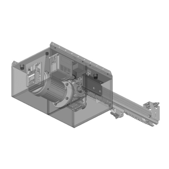
Page 8: Product Description
Product Description The Axess® Pro Series 1101 Overhead Door Opener consists of a drive unit with integrated logic controller, aluminium channel and photo electric beam sensors. Logic Controller Housed alongside the drive motor and gearbox is a set of inverter and intelligent logic controller with fi... -
Page 9: Drive Unit Installation
Drive Unit Installation Drive Unit Pre-assembly The drive unit and track assembly are supplied as two separate parts. The drive sprocket is part of the track assembly. 1. To connect track to the drive unit, remove the front cover. fi g 2. -
Page 10: Control Board Layout
Control Board Layout 24VDC output for powering accessories 3A(max) Drive unit connections Com Terminal for light or lock interface relay drive Light interface relay drive Lock interface relay drive V+ PE Beam power PE Input Terminal V- PE Beam Power COM terminal for inputs terminals 11-16 OPN N/O input terminal STP N/O input terminal... - Page 11 Control Board Layout fi g Owner Installation Instructions Axess® Pro Series 1101...
-
Page 12: Wiring Diagram
Wiring Diagram fi g Axess® Pro Series 1101 Owner Installation Instructions... -
Page 13: Setting Travel Limits
Setting Travel Limits CAUTION: Cables which have a Green/Yellow coloured insulation are for earthing purposes only. Never use these cables for any other purpose. AXESS PRO Firmware #.## This section shows how to set the travel limits. The fi g procedure can be partly completed using a transmitter. - Page 14 Setting Travel Limits Step 3. Setting Close Travel Limit 1. Press CLOSE to move the door to the desired CLOSE To CLS Limit LIMIT. (Or Press button 4 on transmitter) (Fig. 15). 2. Rotate the red CLOSE limit cam until the switch is Adjust, activated (Fig.
-
Page 15: Setting Pedestrian Position
Setting Pedestrian Position Pedestrian Access Position After completing the travel limit set procedure, the Pedestrian Access Position is automatically set to a MENU 10.2 position which is in the middle of the door travel. The Set Pedestrian position can be manually set by following the SETTING PEDESTRIAN POSITION procedure below. -
Page 16: Description Of Standard Operation
Description Of Standard Operation This section describes the standard operation Courtesy Light of the control board with the factory set default With the addition of a light relay module which connects values. across V+ and LGT terminals on the control board, the control board will control a courtesy light. -
Page 17: Parameter Viewing And Editing
Open (OPN) Input Photoelectric Safety Beam (P.E) Input (Activated by OPN terminal with N/O switch, by (Activated by PE terminal with N/C switch) When transmitter button with OPN function assigned or by the P.E input is active, the door is prevented from console’s OPEN button). -
Page 18: Menu Structure
Menu Structure Axess® Pro Series 1101 Owner Installation Instructions... -
Page 19: Control Board Adjustments
Details about the four Auto-Close modes follow. Pedestrian access Auto-Close Automatic Technology strongly recommend using a PE This mode is selected by entering a non-zero Beam for added safety. -
Page 20: Menu 4 Lock Times
Control Board Adjustments Menu 4. Lock Times With the addition of a relay module connected to the control board, the electric lock can be controlled. Lock output can be programmed for both hold and pulse operation and can also be programmed to activate prior to the door motor starting. -
Page 21: Menu 6 Motor Settings
Activity reports opening but will stop the door when closing. This parameter enables activity report outputs. Contact Automatic Technology for more details. Reverses close cycles In this mode, the P.E input has no effect when opening but will cause the door to reverse if activated when closing. - Page 22 Activity report ID Transmitter grouping This parameter sets the ID of the controller that The transmitter store number display format can be is sent with the activity report. Contact Automatic changed to show a grouped format. When grouping Technology for more details. is selected, instead of displaying the store location as a number between 1 and 511, it is displayed as ##$ where ## is the group number and $ is a character...
-
Page 23: Coding Transmitters
Coding Transmitter Up to 511 transmitters can be stored within the openers memory. Each transmitter can be allocated an alpha-numeric ID label up to eleven (11) characters in length and each button can be assigned to one of several control functions. The settings for a transmitter 12 ID NAME/SN are represented in (Fig. -
Page 24: Transmitter Edit Procedure
Transmitter Edit Procedure Editing Transmitter Settings Display Transmitter Record Using the method below, the required transmitters MENU 1 details are displayed. Code Transmitter fi g Step 1. Navigating To “Edit Transmitter” Menu Press NEXT to navigate to Menu 1. Press the SET button (Fig. 29). The Controller will prompt to press one of the transmitter’s buttons. -
Page 25: Transmitter Management
Transmitter Edit Procedure owner. Step 4. Selection Of ID or SN Display 1. Press NEXT/PREV to move the cursor over the ID fi eld. 12 SN 12345 2. Press NEXT to reveal the serial number (Fig. 33). The PED LGT VAC serial number display is provided for additional means of identifi... -
Page 26: Code Operation (Location Empty)
Transmitter Management Once the list is displayed it can be sorted by Store number, ID Label or Serial Number. Use the NEXT or PREV buttons to select sorting method. 14 ID B B SMITH PED LGT VAC NOTE: When sorting by ID label or S/N, only stored transmitters locations are displayed. -
Page 27: Remote Code Set Procedure
Remote Code Set Procedure If a transmitter is already coded into the opener, additional transmitters can be coded without being in direct contact with the opener’s control panel. PRESS Existing NOTE: Only the function of the existing transmitter transmitter button can be assigned to a new transmitter. Please fi... -
Page 28: Diagnostic Tools
Diagnostic Tools Menu 8 The controller provides several diagnostic tools from within the diagnostics menu (menu 8). This section MENU 8 details the function of each tool and its use. Diagnostics Navigating To Diagnostics Menu fi g Press PREV to navigate Menu 8. Press SET to display menu of available functions (Fig. -
Page 29: Menu 8.4 Memory Usage
Diagnostic Tools Menu 8.3 Display History The opener keeps a record of the last 64 events that have taken place. The events include the type of drive Close Complete cycles executed, obstruction detection, various faults, Event# 64 power failures etc. When this tool is selected the screen displays the last event that occurred (Fig. -
Page 30: Memory Tools
Memory Tools The Memory Tools accessed from within Menu 9 are used to clear the controller’s memory. Once selected the PREV or NEXT buttons can be used to view the MENU 9 Memory Tool options. To Execute the displayed option Memory Tools simply press SET (Fig. -
Page 31: Pe Beams
( IR-200TS-RX). Locate the Photo Electric (PE) Beams in a strategic location in the doorway. Automatic Technology recommend that the sensor is placed 100 mm above the fl oor level and as close as possible to the door opening. -
Page 32: Troubleshooting
It is possible that these devices could cause a degree of interference such as to greatly reduce the range of the transmitter. In such an instance please contact your Automatic Technology dealer for assistance. As this is not a warrantable situation but an environmental issue, charges may apply. -
Page 33: System Specifi Cations
System Specifi cations Technical Specifi cations Input voltage 240V AC 50Hz Single phase Motor type Induction Motor voltage 240 V AC Three phase Maximum door size Maximum door height 6000mm Receiver type UHF TrioCode™ Receiver Receiver code storage capacity 511 Transmitters Transmitter frequency 433 MHz Coding type... -
Page 34: Parts List
Parts List When ordering spare parts please quote the order code Number to your installer/dealer Item/description order code Item/description order code 1. Reducer LM-NEM 50 WV 1/40 14500 38. Int tooth lock washer ID 4 11140 2. AC motor 375W 3P 415V delta 14511 39. - Page 35 fi g Owner Installation Instructions Axess® Pro Series 1101...
- Page 36 Maintenance Yearly Whilst your opener does not require any periodic Automatic Technology suggests you contact your door maintenance, the door that it is fi tted to, does. Your professional to perform an annual door service. door is a large, heavy, moving object and should be tested regularly to ensure it is in good condition.
- Page 37 Notes Owner Installation Instructions Axess® Pro Series 1101...
-
Page 38: Warranty And Exclusion Of Liability
1. This warranty is an addition to any non-excludable conditions or warranties that are implied into this contract by relevant statute, including the Trade Practices Act 1974 (Cth). 2. Subject to all of the matters set out below, Automatic Technology (Australia) Pty Ltd (“ATA”) warrants: (a) the Axess® Pro Series Opener for twelve (12) months, (b) all components and accessories for twelve (12) months, from the date of purchase (specifi... - Page 39 Owner Installation Instructions Axess® Pro Series 1101...
- Page 40 © April 2010 Automatic Technology (Australia) Pty Ltd. All rights reserved. Axess® and TrioCode™ are a registered trademark and trademark of Automatic Technology (Australia) Pty Ltd. No part of this document may be reproduced without prior permission. In an ongoing commitment to product quality we reserve the right to change specifi cation without notice.
Need help?
Do you have a question about the Axess Pro Series 1101 and is the answer not in the manual?
Questions and answers