Moxa Technologies EtherDevice EDS-305 Hardware Installation Manual
Ethernet switches
Hide thumbs
Also See for EtherDevice EDS-305:
- Hardware installation manual (18 pages) ,
- Manual (84 pages) ,
- Hardware installation manual (17 pages)
Table of Contents
Advertisement
Quick Links
Advertisement
Table of Contents

Related Manuals for Moxa Technologies EtherDevice EDS-305


Summary of Contents for Moxa Technologies EtherDevice EDS-305
-
Page 1: Moxa Etherdevice Switch
Moxa EtherDevice Switch EDS-305 Hardware Installation Guide Eighth Edition, September 2010 © 2010 Moxa Inc. All rights reserved. Reproduction without permission is prohibited. Fl.4, No.135, Lane 235, Pao-Chiao Rd. Shing Tien City, Taipei, Taiwan, R.O.C. TEL: +886-2-8919-1230 P/N: 1802003050030... -
Page 2: Package Checklist
Overview Moxa’s EtherDevice™ EDS-305 are smart Ethernet switches that provide an economical solution for your Ethernet connections. As an added bonus, the built-in smart alarm function helps system maintainers monitor the health of your Ethernet network. The EDS-305 have a wide operating temperature range of -40 to 75ºC, and are designed to withstand a high degree of vibration and shock. -
Page 3: Panel Layout
Panel Layout EDS-305 Grounding screw Front Panel View Terminal block for power inputs PWR1/PWR2 and relay output Heat dissipation orifices DIP switches Power input PWR1 LED Power input PWR2 LED Fault LED 10/100BaseT(X) Port TP port’s 100 Mbps LED TP port’s 10 Mbps LED Model Name Screw holes for wall mounting DIN-rail Kit... - Page 4 Panel Layout (SC-type) NOTE: The appearance of EDS-305-M-SC EDS-305-S-SC is identical to Front Panel View EDS-305-M-SC Grounding screw Terminal block for power inputs PWR1/PWR2 and relay output Heat dissipation orifices DIP switches Power input PWR1 LED Power input PWR2 LED Fault LED 10/100BaseT(X) Port TP port’s 100 Mbps LED...
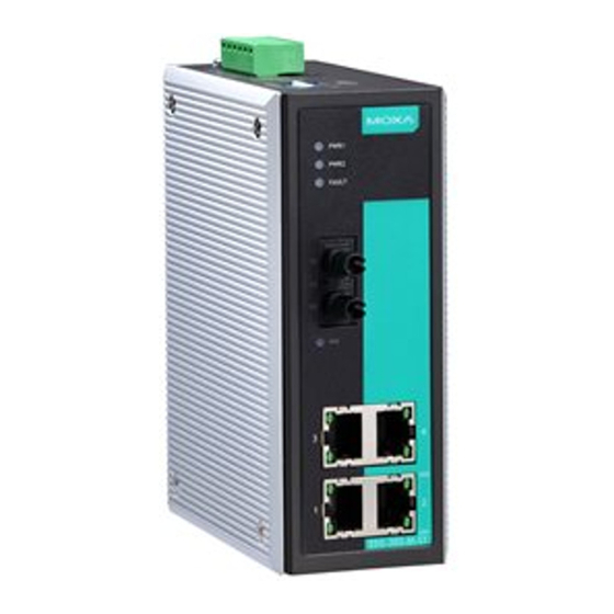
- Page 5 Panel Layout (ST-type) EDS-305-M-ST Grounding screw Front Panel View Terminal block for power input PWR1/PWR2 and relay output Heat dissipation orifices DIP switches Power input PWR1 LED Power input PWR2 LED Fault LED 10/100BaseT(X) Port TP port’s 100 Mbps LED TP port’s 10 Mbps LED Model Name 100BaseFX Port...
-
Page 6: Mounting Dimensions (Unit = Mm)
Mounting Dimensions (unit = mm) 30.00 15.10 19.80 13.10 25.40 9.00 DlN-Rail DlN-Rail Kit 105.00 Front View Side View 18.2 13.9 13.9 DlN-Rail Kit 30.50 7.75 7.75 53.60 Rear View Wall Mounting Kit DIN-rail Mounting The aluminum DIN-rail attachment plate should already be fixed to the back panel of the EDS when you take it out of the box. -
Page 7: Wall Mounting (Optional)
Wall Mounting (optional) For some applications, you will find it convenient to mount the EDS on the wall, as illustrated below. STEP 1: Remove the aluminum DIN-rail attachment plate from the plate EDS’s rear panel, and then ⇒ attach the wall mount plates, as shown in the diagram below. -
Page 8: Wiring Requirements
Wiring Requirements WARNING Do not disconnect modules or wires unless the power supply has been switched off or the area is known to be non-hazardous. The devices may only be connected to the supply voltage shown on the type plate. The devices are designed for operation with a Safety Extra-Low Voltage. -
Page 9: Grounding The Etherdevice Switch
Grounding the EtherDevice Switch Grounding and wire routing help limit the effects of noise due to electromagnetic interference (EMI). Run the ground connection from the ground screw to the grounding surface prior to connecting devices. ATTENTION This product is intended to be mounted to a well-grounded mounting surface, such as a metal panel. -
Page 10: Communication Connections
ATTENTION Before connecting the EDS to the DC power inputs, make sure the DC power source voltage is stable. Communication Connections EDS-305 models have 4 or 5 10/100BaseT(X) Ethernet ports, and 1 or 0 (zero) 100 BaseFX (SC/ST-type connector) fiber ports. 10/100BaseT(X) Ethernet Port Connection The 10/100BaseT(X) ports located on the EDS’s front panel are used to connect to Ethernet-enabled devices. -
Page 11: Redundant Power Inputs
full-duplex transmission. All you need to remember is to connect the Tx (transmit) port of device I to the Rx (receive) port of device II, and the Rx (receive) port of device I to the Tx (transmit) port of device II. If you make your own cable, we suggest labeling the two sides of the same line with the same letter (A-to-A and B-to-B, as shown below, or A1-to-A2 and B1-to-B2). -
Page 12: Dip Switch Settings
DIP Switch Settings EDS-305 Series DIP Switches ON: Enables the corresponding PORT Alarm. If the port’s link fails, the relay will form an open circuit and the fault LED will light up. Off: Disables the corresponding PORT Alarm. The relay will form a closed circuit and the Fault LED will never light up. -
Page 13: Auto Mdi/Mdi-X Connection
Auto MDI/MDI-X Connection The Auto MDI/MDI-X function allows users to connect the EDS’s 10/100BaseTX ports to any kind of Ethernet device, without needing to pay attention to the type of Ethernet cable being used for the connection. This means that you can use either a straight-through cable or cross-over cable to connect the EDS to Ethernet devices. -
Page 14: Switching, Filtering, And Forwarding
Switching, Filtering, and Forwarding Each time a packet arrives at one of the switched ports, a decision is made to either filter or forward the packet. Packets with source and destination addresses belonging to the same port segment will be filtered, constraining those packets to one port, and relieving the rest of the network from the need to process them. -
Page 15: Specifications
Specifications Technology Standards IEEE802.3, 802.3u, 802.3x Forward and Filtering 148810 pps Rate Packet Buffer Memory 256 KB Processing Type Store and Forward, with IEEE802.3x full duplex, back pressure flow control Address Table Size 1K uni-cast addresses Latency Less than 5 μs Interface RJ45 Ports 10/100BaseT(X) auto negotiation speed, F/H duplex... - Page 16 Environmental Operating Temperature 0 to 60ºC (32 to 140ºF) -40 to 75ºC (-40 to 167ºF) for -T models Storage Temperature -40 to 85ºC (-40 to 185ºF) Ambient Relative Humidity 5 to 95% (non-condensing) Regulatory Approvals Safety UL60950, UL 508, CSA C22.2 No. 60950, EN60950 Hazardous Location UL/cUL Class I, Division 2, Groups A, B, C and D ATEX, Zone 2, Ex nC nL IIC T4...
Need help?
Do you have a question about the EtherDevice EDS-305 and is the answer not in the manual?
Questions and answers