
Related Manuals for Moxa Technologies EtherDevice EDS-305-T


Summary of Contents for Moxa Technologies EtherDevice EDS-305-T
- Page 1 EDS-305 Hardware Installation Guide Moxa EtherDevice Switch Ninth Edition, April 2014 2014 Moxa Inc. All rights reserved. P/N: 1802003050031...
-
Page 2: Package Checklist
Overview Moxa’s EtherDevice™ EDS-305 are smart Ethernet switches that provide an economical solution for your Ethernet connections. As an added bonus, the built-in smart alarm function helps system maintainers monitor the health of your Ethernet network. The EDS-305 have a wide operating temperature range of -40 to 75°C, and are designed to withstand a high degree of vibration and shock. -
Page 3: Panel Layout
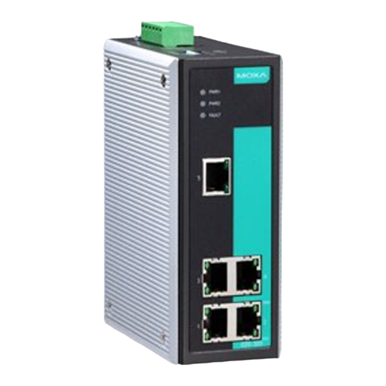
Panel Layout 1. Grounding screw 2. Terminal block for power inputs PWR1/PWR2 and relay output 3. Heat dissipation orifices 4. DIP switches 5. Power input PWR1 LED 6. Power input PWR2 LED 7. Fault LED 8. 10/100BaseT(X) Port 9. TP port’s 100 Mbps LED 10. - Page 4 Panel Layout (SC-type) NOTE: The appearance of EDS-305-S-SC is identical to EDS-305-M-SC 1. Grounding screw 2. Terminal block for power inputs PWR1/PWR2 and relay output 3. Heat dissipation orifices 4. DIP switches 5. Power input PWR1 LED 6. Power input PWR2 LED 7.
- Page 5 Panel Layout (ST-type) 1. Grounding screw 2. Terminal block for power input PWR1/PWR2 and relay output 3. Heat dissipation orifices 4. DIP switches 5. Power input PWR1 LED 6. Power input PWR2 LED 7. Fault LED 8. 10/100BaseT(X) Port 9. TP port’s 100 Mbps LED 10.
-
Page 6: Mounting Dimensions
Mounting Dimensions Unit = mm (inch) - 6 -... -
Page 7: Din-Rail Mounting
DIN-Rail Mounting The aluminum DIN-rail attachment plate should already be fixed to the back panel of the EDS when you take it out of the box. If you need to reattach the DIN-rail attachment plate, make sure the stiff metal spring is situated towards the top, as shown in the figures below. -
Page 8: Atex Information
STEP 3: Once the screws are fixed in the wall, insert the four screw heads through the large parts of the keyhole-shaped apertures, and then slide the EDS downwards, as indicated. Tighten the four screws for added stability. ATEX Information 1. -
Page 9: Grounding The Etherdevice Switch
WARNING This unit is a built-in type. When the unit is installed in another piece of equipment, the equipment enclosing the unit must comply with fire enclosure regulation IEC 60950/EN60950 (or similar regulation). WARNING Safety First! Be sure to disconnect the power cord before installing and/or wiring your Moxa EtherDevice Switch. -
Page 10: Wiring The Alarm Contact
Wiring the Alarm Contact The Alarm Contact consists of the two middle contacts of the terminal block on EDS’s top panel. You may refer to the next section for detailed instructions on how to connect the wires to the terminal block connector, and how to attach the terminal block connector to the terminal block receptor. -
Page 11: Communication Connections
Communication Connections EDS-305 models have 4 or 5 10/100BaseT(X) Ethernet ports, and 1 or 0 (zero) 100 BaseFX (SC/ST-type connector) fiber ports. 10/100BaseT(X) Ethernet Port Connection The 10/100BaseT(X) ports located on the EDS’s front panel are used to connect to Ethernet-enabled devices. Below we show pinouts for both MDI (NIC-type) ports and MDI-X (HUB/Switch-type) ports, and also show cable wiring diagrams for straight-through and cross-over Ethernet cables. -
Page 12: Redundant Power Inputs
100BaseFX Ethernet Port Connection The concept behind the SC/ST port and cable is quite straightforward. Suppose you are connecting devices I and II. Contrary to electrical signals, optical signals do not require a circuit in order to transmit data. Consequently, one of the optical lines is used to transmit data from device I to device II, and the other optical line is used transmit data from device II to device I, for full-duplex transmission. -
Page 13: Dip Switch Settings
The Alarm Contact has two terminals that form a Fault circuit for connecting to an alarm system. The two wires attached to the Fault contacts form an open circuit when (1) EDS has lost power from one of the DC power inputs, or (2) one of the ports for which the corresponding PORT ALARM DIP Switch is set to ON is not properly connected. -
Page 14: Fiber Ports
Fiber Ports The EDS’s fiber switched ports operate at a fixed 100 Mbps speed and full-duplex mode to provide the best performance. The fiber ports are factory-built as either a multi-mode or single-mode SC/ST connector. Consequently, you should use fiber cables that have SC/ST connectors at both ends. -
Page 15: Switching And Address Learning
Switching and Address Learning The EDS has an address table that can hold up to 1K node addresses, which makes it suitable for use with large networks. The address tables are self-learning, so that as nodes are added or removed, or moved from one segment to another, the EDS automatically keeps up with new node locations. - Page 16 Recommended Diameter 50/125 9/125 9/125 9/125 (Core/Cladding) μm (1 dB/km, 800 MHz x km) Power Input Voltage 12 to 48 VDC, redundant inputs Input Current EDS-305: 0.13 A @ 24 V EDS-305-M/S: 0.17 A @ 24 V Connection Removable “6-pin” Terminal Block Overload Current 1.1 A Protection...
Need help?
Do you have a question about the EtherDevice EDS-305-T and is the answer not in the manual?
Questions and answers