Moxa Technologies EDS-510E Series Hardware Installation Manual
Etherdevice switch
Hide thumbs
Also See for EDS-510E Series:
- User manual (116 pages) ,
- User manual (38 pages) ,
- User manual (123 pages)

Subscribe to Our Youtube Channel
Related Manuals for Moxa Technologies EDS-510E Series


Summary of Contents for Moxa Technologies EDS-510E Series
-
Page 1: Hardware Installation Guide
EDS-510E Series Hardware Installation Guide Moxa EtherDevice™ Switch First Edition, July 2013 2013 Moxa Inc. All rights reserved. P/N: 1802005100040... -
Page 2: Package Checklist
• 1 EDS-510E Ethernet switch • Hardware installation guide • Documentation and software CD • Moxa product warranty statement • USB cable • Protective caps for unused ports Features • 2 Gigabit Ethernet ports for redundant ring and 1 Gigabit Ethernet port for uplink solution •... -
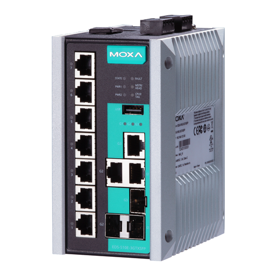
Page 3: Panel Views Of Eds-510E
Panel Views of EDS-510E Front Panel Front Panel 1. 1 to 7 port status LED 2. 1 to 7: 10/100BaseT(X) port 3. System status LED: • STATE LED indicator • PWR1 LED indicator • PWR2 LED indicator • FAULT LED indicator •... -
Page 4: Mounting Dimensions
Mounting Dimensions Unit = mm (inch) - 4 -... -
Page 5: Din-Rail Mounting
DIN-Rail Mounting The metal DIN-rail kit is fixed to the back panel of the EDS-510E when you take it out of the box. Mount the EDS-510E on corrosion-free mounting rails that meet the EN 60715 standard. Installation STEP 1—Insert the upper lip of the DIN rail into the DIN-rail mounting kit. STEP 2—Press the EDS-510E t towards the DIN rail until it snaps into place. -
Page 6: Wall Mounting (Optional)
Wall Mounting (Optional) For some applications, you will find it convenient to mount Moxa EDS-510E on the wall, as shown in the following illustrations: STEP 1—Remove the aluminum DIN rail attachment plate from the rear panel of the EDS-510E, and then... -
Page 7: Grounding The Moxa Eds-510E
ATTENTION Safety First! Be sure to disconnect the power cord before installing and/or wiring your Moxa EtherDevice Switch. Calculate the maximum possible current in each power wire and common wire. Observe all electrical codes dictating the maximum current allowable for each wire size. -
Page 8: Wiring The Redundant Power Inputs
FAULT: The two contacts of the 6-pin terminal block connector are used to detect user-configured events. The two wires attached to the fault contacts form an open circuit when a user-configured event is triggered. If a user-configured event does not occur, the fault circuit remains closed. -
Page 9: Usb Console Connection
ABC-02-USB Installation Plug the ABC-02-USB into the USB storage port of the Moxa EDS-510E. Securing the ABC-02-USB on the wall with an M4 screw is suggested. USB Storage Port (Type A Connector) Pinouts... -
Page 10: 1000Baset Ethernet Port Connection
(straight-through or cross-over), and the type of device (NIC-type or HUB/Switch-type) connected to the port. In what follows, we give pinouts for both MDI (NIC-type) ports and MDI-X (HUB/Switch-type) ports. We also give cable wiring diagrams for straight-through and cross-over Ethernet cables. RJ45 (8-pin, MDI) Port Pinouts Signal RJ45 (8-pin, MDI-X) Port Pinouts... -
Page 11: Reset Button
The gigabit Ethernet ports on the EDS-510E are 100/1000BaseSFP Fiber ports, which require using the 100M or 1G mini-GBIC fiber transceivers to work properly. Moxa provides completed transceiver models for different distance requirement. The concept behind the LC port and cable is quite straightforward. -
Page 12: Turbo Ring Dip Switch Settings
Turbo Ring DIP Switch Settings EDS-510E series are plug-and-play managed redundant Ethernet switches. The proprietary Turbo Ring protocol was developed by Moxa to provide better network reliability and faster recovery time. Moxa Turbo Ring’s recovery time is less than 300 ms (Turbo Ring) or 20 ms (Turbo Ring V2) —compared to a 3- to 5-minute recovery time for commercial... -
Page 13: Led Indicators
Ring Master, these EDS-510E switches will auto-negotiate to determine which one will be the Ring Master. LED Indicators The front panel of the Moxa EDS-510E contains several LED indicators. The function of each LED is described in the following table: Color... - Page 14 Color Status Description 1. The switch has become the Ring Master of the Turbo Ring. 2. The Head of the Turbo Chain, after the Turbo Ring or the Turbo Chain Blinking is down. 3. The switch is set as Turbo Chain’s Member and the corresponding chain port is down.
-
Page 15: Specifications
Temperature -40 to 75°C (-40 to 167°F) for T models Storage -40 to 85°C (-40 to 185°F) Temperature Ambient Relative 5 to 95% (non-condensing) Humidity Altitude Up to 2000m Note: Please contact Moxa if you require products - 15 -... - Page 16 Shock IEC 60068-2-27 Free Fall IEC 60068-2-32 Vibration IEC 60068-2-6 Warranty Warranty 5 years Technical Support Contact Information www.moxa.com/support Moxa Americas: Moxa China (Shanghai office): Toll-free: 1-888-669-2872 Toll-free: 800-820-5036 Tel: 1-714-528-6777 Tel: +86-21-5258-9955 Fax: 1-714-528-6778 Fax: +86-21-5258-5505 Moxa Europe: Moxa Asia-Pacific:...
Need help?
Do you have a question about the EDS-510E Series and is the answer not in the manual?
Questions and answers