
Subscribe to Our Youtube Channel
Related Manuals for Moxa Technologies EDS-G4012 Series


Summary of Contents for Moxa Technologies EDS-G4012 Series
- Page 1 EDS-G4012 Series Quick Installation Guide Moxa EtherDevice™ Switch Version 1.2, April 2024 Technical Support Contact Information www.moxa.com/support 2024 Moxa Inc. All rights reserved. P/N: 1802040120112 *1802040120112*...
-
Page 2: Package Checklist
Package Checklist The EDS-G4012 Series industrial DIN-rail EtherDevice Switch (EDS) is shipped with the following items. If any of these items are missing or damaged, please contact your customer service representative for assistance. • 1 EDS-G4012 Ethernet switch • Quick installation guide (printed) •... -
Page 3: Mounting Dimensions
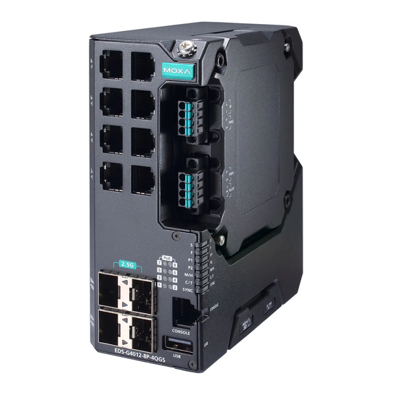
5. 100/1000BaseSFP LED 12. 100/1000/2500BaseSFP port, indicator QG1 to QG4 6. Grounding connector screw 13. SmartPoE LED indicator of PoE 7. Terminal blocks for power ports input, digital input, and relay 14. 1000/2500BaseSFP LED output indicator Bottom Panel View 1. microSD card slot 2. -
Page 4: Din Rail Mounting
DIN-rail Mounting The DIN-rail mounting kit is fixed to the back panel of the EDS device when you take it out of the box. Mount the EDS device on corrosion- free mounting rails that meet the EN 60715 standard. Installation STEP 1—Insert the upper lip of the DIN rail into the DIN-rail mounting kit. -
Page 5: Wall Mounting (Optional)
Wall Mounting (Optional) For some applications, you will find it convenient to mount the Moxa EDS device on a wall, as shown in the following illustrations: STEP 1—Remove the DIN-rail attachment plate from the rear panel of the EDS device, and then attach the wall mount plates with M3 screws. - Page 6 ATTENTION In order to ensure reliable operations, please make sure the operating temperature of the environment does not exceed the specifications. When mounting an EDS device with other operating units in a cabinet without forced ventilation, a minimum of 4 cm space on both the left and right of the switch is recommended.
-
Page 7: Wiring The Relay Contact
Suggested Wire Type for Wiring Relay Contact (R), Digital Input (DI), and Power Inputs (P1/P2) The EDS device includes two 4-pins 3.5 mm pin-pitch terminal blocks. When wiring the relay contact (RELAY), digital input (DI), and power inputs (P1/P2), we suggest using the following cable type and the corresponding pin type cable terminals: •... -
Page 8: Wiring The Redundant Power Inputs
Relay: The two contacts of the 4-pin terminal block connector are used to detect user-configured events. The two wires attached to the relay contact form an open circuit when a user-configured event is triggered or there is no power supply to the switch. If a user- configured event does not occur, the relay circuit remains closed. -
Page 9: Wiring The Digital Inputs
Wiring the Digital Inputs The EDS device has one set of digital input (DI). The DI consists of two contacts of the 4-pin terminal block connector on the EDS's right-side panel. Refer to the instructions and diagram below on how to connect the wires to the terminal block connector on the receptor. -
Page 10: Communication Connections
Communication Connections Each EDS-G4012 Series switch has various types of communication ports: • RJ45 console port (RS-232 interface) • USB storage port (type A connector) • 10/100/1000BaseT(X) Ethernet ports • 10/100/1000BaseT(X) or 100/1000BaseSFP combo ports • 1000/2500BaseSFP slots • microSD card slot... -
Page 11: Fiber Port
100/1000BaseSFP and 1000/2500BaseSFP (mini-GBIC) Fiber Port The fiber ports on the switch are 100/1000BaseSFP and 1000/2500BaseSFP fiber ports, which require 100M, 1G, or 2.5G mini- GBIC fiber transceivers to work properly. The concept behind the LC port and cable is quite straightforward. Suppose that you are connecting devices I and II;... - Page 12 There are five Hardware DIP Switches for Turbo Ring on the bottom panel of the EDS device that can help setup the Turbo Ring easily within seconds. If you do not want to use a hardware DIP switch to setup the Turbo Ring, you can use a web browser, telnet, or console to disable this function.
-
Page 13: Device Led Indicators
LED Indicators The front panel of the Moxa EDS-G4012 Series contains several LED indicators. The function of each LED is described in the following table: Device LED Indicators Color State Description When system has passed power- on self-test (POST) and is ready to run. - Page 14 Color State Description 1. The switch has become the Master of Turbo Ring after the Turbo Ring has gone down. 2. The switch is set as the Head of Turbo Chain and the Turbo Chain has gone down. 3. The switch is set as a Turbo Blinking Ring Member and the (4 times/sec)
- Page 15 Smart PoE LED Indicators Color State Description When the port is connected to: • Single signature (PD) Class 5 to 8 • Dual signature (PD) Class 1 to 5 Green • PD in Force Power mode 1. When the power is not being supplied to a powered device (PD) 2.
-
Page 16: Specifications
Color State Description When the port is inactive or link down. When the port is active and links at 2500Mbps. When the port’s data is being Green Blinking transmitted at 2500Mbps. When the port is inactive or link 1000M/ down. 2500M When the port is active and (SFP port) - Page 17 Module -HV/-HV-T models: PWR-105-HV-I -LVA/-LVA-T models: PWR-101-LV-BP-I -LVB/-LVB-T models: PWR-103-LV-VB-I Note The EDS-G4012 Series supports modular power supplies. The model names and power parameters are determined by the installed power module. For example: EDS-G4012-T + PWR-100-LV = EDS-G4012-LV-T EDS-G4012-T + PWR-105-HV-I = EDS-G4012-HV- If you install a different power module, refer to the specifications of the corresponding model.
- Page 18 Reverse Polarity Present Protection Connection 2 removable 4-contact terminal blocks Physical Characteristics Housing Metal, IP40 protection Dimension 55 x 140 x 122.5 mm (2.17 x 5.51 x 4.82 in) Weight EDS-G4012-4GC (-T) models: 881.5 g (1.94 lb) EDS-G4012-8P-4QGS (-T) models: 972 g (2.14 lb) Installation DIN-rail mounting, wall mounting (with optional kit)
-
Page 19: Warning - Explosion Hazard
Hazardous Location Information (except for PoE and HV models) ATEX information II 3G Ex ec nC IIC T4 Gc UL 22 ATEX 2741X Ambient Range: -40°C ≤ Tamb ≤ +75°C for -T models Ambient Range: -10°C ≤ Tamb ≤ +60°C for models without “-T”...
Need help?
Do you have a question about the EDS-G4012 Series and is the answer not in the manual?
Questions and answers