Moxa Technologies EtherDevice EDS-G512E-8PoE Series Hardware Installation Manual
Hide thumbs
Also See for EtherDevice EDS-G512E-8PoE Series:
- User manual (116 pages) ,
- User manual (38 pages) ,
- User manual (123 pages)

Related Manuals for Moxa Technologies EtherDevice EDS-G512E-8PoE Series


Summary of Contents for Moxa Technologies EtherDevice EDS-G512E-8PoE Series
- Page 1 EDS-G512E-8PoE Series Hardware Installation Guide Moxa EtherDevice™ Switch Second Edition, July 2015 2015 Moxa Inc. All rights reserved. P/N: 1802005120011 *1802005120011* www.ipc2u.ru www.moxa.pro...
-
Page 2: Package Checklist
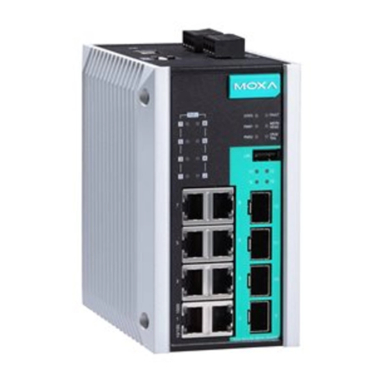
Package Checklist The EDS-G512E-8PoE is shipped with the following items. If any of these items are missing or damaged, please contact your customer service representative for assistance. • 1 EDS-G512E-8PoE-4GSFP or EDS-G512E-8PoE-4GSFP-T Ethernet switch • Hardware installation guide • Documentation and software CD •... - Page 3 Panel Views of EDS-G512E-8PoE Series Front Panel Front Panel 1. 1000BaseT(X) LED indicator 2. 10/100BaseT(X) LED indicator 3. 10/100/1000BaseT(X) ports Port 1 to 8 4. System status LED: • STATE LED indicator • PWR1 LED indicator • PWR2 LED indicator •...
-
Page 4: Mounting Dimensions
Mounting Dimensions Unit = mm (inch) - 4 - www.ipc2u.ru www.moxa.pro... -
Page 5: Din-Rail Mounting
DIN-Rail Mounting The metal DIN-rail kit is fixed to the back panel of the EDS-G512E-8PoE series when you take it out of the box. Mount the EDS-G512E-8PoE series on corrosion-free mounting rails that meet the EN 60715 standard. Installation STEP 1—Insert the upper lip of the DIN rail into the DIN-rail mounting kit. -
Page 6: Wiring Requirements
STEP 2—Mounting the EDS-G512E-8PoE series on the wall requires 4 screws. Use the EDS-G512E-8PoE series, with wall mount plates attached, as a guide to mark the correct locations of the 4 screws. The heads of the screws should be less than 6.0 mm in diameter, and the shafts should be less than 3.5 mm in diameter, as shown in the figure on at right. -
Page 7: Wiring The Relay Contact
ATTENTION Safety First! Be sure to disconnect the power cord before installing and/or wiring your Moxa EtherDevice Switch. Calculate the maximum possible current in each power wire and common wire. Observe all electrical codes dictating the maximum current allowable for each wire size. If the current goes above the maximum ratings, the wiring could overheat, causing serious damage to your equipment. -
Page 8: Wiring The Redundant Power Inputs
Wiring the Redundant Power Inputs The EDS-G512E-8PoE series has two sets of power inputs—power input 1 and power input 2. The top and front views of one of the terminal block connectors are shown here. STEP 1: Insert the negative/positive DC wires into the V-/V+ terminals, respectively. -
Page 9: 1000Baset Ethernet Port Connection
USB Console Port (Type B Connector) Pinouts Description D– (Data -) VCC (+5V) D+ (Data+) GND (Ground) USB Storage Connection The EDS-G512E-8PoE series has one USB storage port (type A connector) on the front panel. Use Moxa ABC-02-USB-T automatic backup configurator to connect the EDS-G512E-8PoE's USB storage port for configuration backup, firmware upgrade or system log file backup. -
Page 10: Reset Button
100/1000BaseSFP (mini-GBIC) Fiber Port The Gigabit Ethernet ports on the EDS-G512E-8PoE series are 100/1000BaseSFP Fiber ports, which require using the 100M or 1G mini-GBIC fiber transceivers to work properly. Moxa provides completed transceiver models for different distance requirement. The concept behind the LC port and cable is quite straightforward. Suppose that you are connecting devices I and II;... -
Page 11: Turbo Ring Dip Switch Settings
Turbo Ring DIP Switch Settings EDS-G512E-8PoE series are plug-and-play managed redundant Ethernet switches. The proprietary Turbo Ring protocol was developed by Moxa to provide better network reliability and faster recovery time. Moxa Turbo Ring’s recovery time is less than 300 ms (Turbo Ring) or 50 ms (Turbo Ring V2) —compared to a 3- to 5-minute recovery time for commercial switches—decreasing the possible loss caused by network failures in an industrial setting. -
Page 12: Led Indicators
NOTE You must enable the Turbo Ring function first before using the DIP switch to activate the Master and Coupler functions. NOTE If you do not enable any of the EDS-G512E-8PoE series switches to be the Ring Master, the Turbo Ring protocol will automatically choose the EDS-G512E-8PoE series with the smallest MAC address range to be the Ring Master. - Page 13 Color Status Description 1. The switch is set as the Master of the Turbo Ring, or as the Head of the Turbo Chain. 2. POST H.W. Fail (+Stat on and Fault blinking). 1. The switch has become the Ring Master of the Turbo Ring. 2.
-
Page 14: Specifications
Smart PoE LED Indicators Color Status Description PoE port is connected to PoE device, using the 802.3af standard Amber No PoE power output PoE port is connected to PoE device, using the 802.3at standard Smart PoE+ GREEN No PoE power output Indicators PoE power failure: - Once/second: PoE detection failure... - Page 15 Total Power Budget 240 W PoE Output Voltage 46 to 57 VDC (depends on external power supply) Max. Output Power 15.4 W in 802.3af, 30 W in 802.3at, 36 W in high power mode Max. Output 350 mA in 802.3af, 600 mA in 802.3at, 720 mA in Current high power mode Overload Current...
- Page 16 ATTENTION This device complies with Part 15 of the FCC rules. Operation is subject to the following conditions: 1. This device may not cause harmful interference. 2. This device must accept any interference received including interference that may cause undesired operation. Technical Support Contact Information www.moxa.com/support Moxa Americas:...
Need help?
Do you have a question about the EtherDevice EDS-G512E-8PoE Series and is the answer not in the manual?
Questions and answers