
Related Manuals for Moxa Technologies EtherDevice EDS-30


Summary of Contents for Moxa Technologies EtherDevice EDS-30
- Page 1 EDS-308/309 Hardware Installation Guide Moxa EtherDevice Switch Ninth Edition, April 2014 2014 Moxa Inc. All rights reserved. P/N: 1802003083011...
-
Page 2: Package Checklist
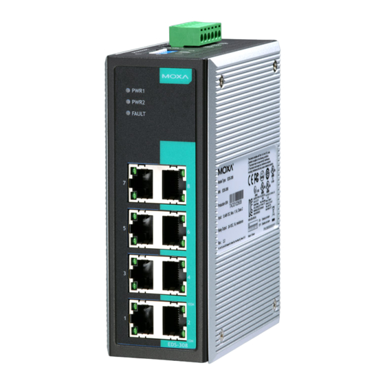
Overview Moxa EtherDevice™ EDS-308/309 Series, which consists of 9-,and 8-port smart Ethernet switches, provides an economical solution for your Ethernet connections. As an added bonus, the built-in smart alarm function helps system maintainers monitor the health of your Ethernet network. EDS-308/309 switches have a wide operating temperature range of -40 to 75°C, and are designed to withstand a high degree of vibration and shock. - Page 3 EDS-308 Panel Layout 1. Grounding screw 2. Terminal block for power inputs PWR1/PWR2 and relay output 3. Heat dissipation orifices 4. DIP switches 5. Power input PWR1 LED 6. Power input PWR2 LED 7. Fault LED 8. 10/100BaseT(X) Port 9. TP port’s 100 Mbps LED 10.
- Page 4 EDS-308 Panel Layout (SC-type) NOTE: The appearance of EDS-308-S-SC is identical to EDS-308-M-SC, and the appearance of EDS-308-SS-SC is identical to EDS-308-MM-SC. 1. Grounding screw 2. Terminal block for power inputs PWR1/PWR2 and relay output 3. Heat dissipation orifices 4. DIP switches 5.
- Page 5 EDS-309 Panel Layout (SC-type) 1. Grounding screw 2. Terminal block for power inputs PWR1/PWR2 and relay output 3. Heat dissipation orifices 4. DIP switches 5. Power input PWR1 LED 6. Power input PWR2 LED 7. Fault LED 8. 10/100BaseT(X) Port 9.
- Page 6 EDS-308/309 Panel Layout (ST-type) 1. Grounding screw 2. Terminal block for power input PWR1/PWR2 and relay output 3. Heat dissipation orifices 4. DIP switches 5. Power input PWR1 LED 6. Power input PWR2 LED 7. Fault LED 8. 10/100BaseT(X) Port 9.
-
Page 7: Mounting Dimensions
Mounting Dimensions Unit = mm (inch) - 7 -... -
Page 8: Din-Rail Mounting
DIN-Rail Mounting The aluminum DIN-Rail attachment plate should already be fixed to the back panel of EDS-308/309 when you take it out of the box. If you need to reattach the DIN-Rail attachment plate, make sure the stiff metal spring is situated towards the top, as shown in the figures below. STEP 1: STEP 2: Insert the top of the DIN-Rail into... -
Page 9: Atex Information
STEP 3: Once the screws are fixed in the wall, insert the four screw heads through the large parts of the keyhole-shaped apertures, and then slide EDS-308/309 downwards, as indicated. Tighten the four screws for added stability. ATEX Information 1. Certificate number DEMKO 08 ATEX 0812123x 2. - Page 10 WARNING This unit is a built-in type. When the unit is installed in another piece of equipment, the equipment enclosing the unit must comply with fire enclosure regulation IEC 60950/EN60950 (or similar regulation). WARNING Safety First! Be sure to disconnect the power cord before installing and/or wiring your Moxa EtherDevice Switch.
-
Page 11: Wiring The Alarm Contact
Wiring the Alarm Contact The Alarm Contact consists of the two middle contacts of the terminal block on EDS’s top panel. You may refer to the next section for detailed instructions on how to connect the wires to the terminal block connector, and how to attach the terminal block connector to the terminal block receptor. -
Page 12: Communication Connections
Communication Connections 10/100BaseT(X) Ethernet Port Connection The 10/100BaseT(X) ports located on the EDS’s front panel are used to connect to Ethernet-enabled devices. Below we show pinouts for both MDI (NIC-type) ports and MDI-X (HUB/Switch-type) ports, and also show cable wiring diagrams for straight-through and cross-over Ethernet cables. -
Page 13: Redundant Power Inputs
suggest labeling the two sides of the same line with the same letter (A-to-A and B-to-B, as shown below, or A1-to-A2 and B1-to-B2). SC-Port Pinouts SC-Port to SC-Port Cable Wiring ST-Port Pinouts ST-Port to ST-Port Cable Wiring ATTENTION This is a Class 1 Laser/LED product. To avoid causing serious damage to your eyes, do not stare directly into the Laser Beam. -
Page 14: Dip Switch Settings
DIP Switch Settings EDS-308 Series DIP Switches EDS-309 Series DIP Switches Enables the corresponding PORT Alarm. If the port’s link fails, the relay will form an open circuit and the fault LED will light up. Off: Disables the corresponding PORT Alarm. The relay will form a closed circuit and the Fault LED will never light up. -
Page 15: Switching, Filtering, And Forwarding
Switching, Filtering, and Forwarding Each time a packet arrives at one of the switched ports, a decision is made to either filter or forward the packet. Packets with source and destination addresses belonging to the same port segment will be filtered, constraining those packets to one port, and relieving the rest of the network from the need to process them. - Page 16 Interface RJ45 Ports 10/100BaseT(X) auto negotiation speed, F/H duplex mode, and auto MDI/MDI-X connection Fiber Ports 100BaseFX ports (SC/ST connector) LED Indicators Power, Fault, 10/100 DIP Switch Port break alarm mask Alarm Contact One relay output with current carrying capacity of 1A @ 24 VDC Optical Fiber Multi...
- Page 17 EN61000-4-6 (CS), Level 3 Shock IEC60068-2-27 Free Fall IEC60068-2-32 Vibration IEC60068-2-6 WARRANTY 5 years Technical Support Contact Information www.moxa.com/support Moxa Americas: Moxa China (Shanghai office): Toll-free: 1-888-669-2872 Toll-free: 800-820-5036 Tel: 1-714-528-6777 Tel: +86-21-5258-9955 Fax: 1-714-528-6778 Fax: +86-21-5258-5505 Moxa Europe: Moxa Asia-Pacific: Tel: +49-89-3 70 03 99-0 Tel:...
Need help?
Do you have a question about the EtherDevice EDS-30 and is the answer not in the manual?
Questions and answers