Moxa Technologies EDS-316 EtherDevice Hardware Installation Manual
Hide thumbs
Also See for EDS-316 EtherDevice:
- Manual (84 pages) ,
- Quick installation manual (19 pages)

Subscribe to Our Youtube Channel
Related Manuals for Moxa Technologies EDS-316 EtherDevice


Summary of Contents for Moxa Technologies EDS-316 EtherDevice
-
Page 1: Hardware Installation Guide
EDS-316 Hardware Installation Guide Moxa EtherDevice Switch Fourth Edition, April 2014 2014 Moxa Inc. All rights reserved. P/N: 1802003160011... -
Page 2: Package Checklist
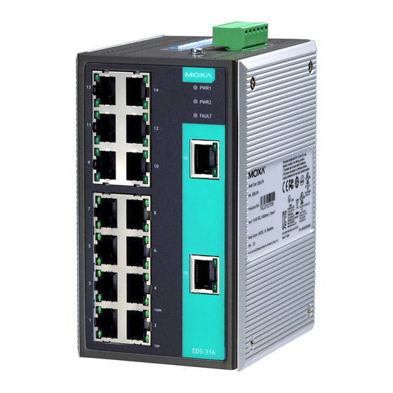
Overview The Moxa EtherDevice™ EDS-316 Series of 16-port smart Ethernet switches provides an economical solution for your Ethernet connections. As an added bonus, the built-in smart alarm function helps system maintainers monitor the health of your Ethernet network. EDS-316 has a wide operating temperature range of -40 to 75°C, and is designed to withstand a high degree of vibration and shock. - Page 3 Panel Layout of EDS-316 (standard-type) 1. Grounding screw 2. Terminal block for power input (PWR1, PWR2) and relay output 3. Heat dissipation orifices 4. DIP switches (EDS-316 has 18 DIP switches in total; 2 DIP switches are reserved) 5. Power input PWR1 LED 6.
- Page 4 Panel Layout of EDS-316 (SC-type) Product models not shown here: EDS-316-S-SC is identical to EDS-316-M-SC. EDS-316-SS-SC and EDS-316-MS-SC are identical to EDS-316-MM-SC. 1. Grounding screw 2. Terminal block for power input (PWR1, PWR2) and relay output 3. Heat dissipation orifices 4.
- Page 5 Panel Layout of EDS-316 (ST-type) 1. Grounding screw 2. Terminal block for power input (PWR1, PWR2) and relay output 3. Heat dissipation orifices 4. DIP switches (EDS-316 has 18 DIP switches in total; 2 DIP switches are reserved) 5. Power input PWR1 LED 6.
-
Page 6: Mounting Dimensions
Mounting Dimensions Unit = mm (inch) DIN-Rail Mounting The aluminum DIN-Rail attachment plate should already be fixed to the back panel of EDS-316 when you take it out of the box. If you need to reattach the DIN-Rail attachment plate, make sure the stiff metal spring is situated towards the top, as shown in the figures below. -
Page 7: Wall Mounting (Optional)
Wall Mounting (optional) For some applications, you will find it convenient to mount EDS-316 on the wall, as illustrated in the figure. STEP 1: Remove the aluminum DIN-Rail attachment plate from EDS-316’s rear panel, and then attach the wall mount plates, as shown in the figure. -
Page 8: Wiring Requirements
Wiring Requirements WARNING Do not disconnect modules or wires unless the power supply has been switched off or the area is known to be non-hazardous. The devices may only be connected to the supply voltage shown on the type plate. The devices are designed for operation with a Safety Extra-Low Voltage. -
Page 9: Wiring The Redundant Power Inputs
• Keep input wiring and output wiring separated. • It is strongly advised that you label wiring to all devices in the system when necessary. Grounding Moxa EtherDevice Switch Grounding and wire routing help limit the effects of noise due to electromagnetic interference (EMI). -
Page 10: Communication Connections
ATTENTION Before connecting EDS to the DC power inputs, make sure the DC power source voltage is stable. Communication Connections EDS-316 models have 14, 15, or 16 10/100BaseT(X) Ethernet ports, and 2, 1, or 0 (zero) 100BaseFX (SC/ST-type connector) fiber ports. 10/100BaseT(X) Ethernet Port Connection The 10/100BaseT(X) ports located on EDS’s front panel are used to connect to Ethernet-enabled devices. -
Page 11: Redundant Power Inputs
All you need to remember is to connect the Tx (transmit) port of device I to the Rx (receive) port of device II, and the Rx (receive) port of device I to the Tx (transmit) port of device II. If you make your own cable, we suggest labeling the two sides of the same line with the same letter (A-to-A and B-to-B, as shown below, or A1-to-A2 and B1-to-B2). -
Page 12: Dip Switch Settings
DIP Switch Settings EDS-316 Series DIP Switches DIP Switch Setting Description Enables the corresponding PORT Alarm. If the port’s link fails, the relay will form an open circuit Port Alarm and the fault LED will light up. Function Disables the corresponding PORT Alarm. The (P1 to P16) relay will form a closed circuit and the Fault LED will never light up. -
Page 13: Auto Mdi/Mdi-X Connection
Auto MDI/MDI-X Connection The Auto MDI/MDI-X function allows users to connect EDS-316’s 10/100BaseTX ports to any kind of Ethernet device, without needing to pay attention to the type of Ethernet cable being used for the connection. This means that you can use either a straight-through cable or cross-over cable to connect EDS-316 to Ethernet devices. -
Page 14: Switching And Address Learning
Packets that are used in maintaining the operation of the network (such as the occasional multi-cast packet) are forwarded to all ports. EDS-316 operates in the store-and-forward switching mode, which eliminates bad packets and enables peak performance to be achieved when there is heavy traffic on the network. -
Page 15: Regulatory Approvals
Optical Fiber 100 BaseFX Multi-mode Single-mode Single-mode, 80 km Wavelength 1300 nm 1310 nm 1550 nm Max. TX -10 dBm 0 dBm 0 dBm Min. TX -20 dBm -5 dBm -5 dBm RX Sensitivity -32 dBm -34 dBm -34 dBm Link Budget 12 dB 29 dB... -
Page 16: Ordering Information
Ordering Information Ordering Code Definition EDS-316-AA-BB[-CC][-T] Fiber Port FO Connector Transmission Operating distance Temperature 1 Multi Mode SC: SC Connector 80: 80 km -T: Wide 1 Single Mode ST: ST Connector (1 or 2 ports) operating Temp. 2 Multi Mode 40/80: 40/80 of -40 to 75°C 2 Single Mode...
Need help?
Do you have a question about the EDS-316 EtherDevice and is the answer not in the manual?
Questions and answers