
Related Manuals for Moxa Technologies EtherDevice EDS-510A-3GT


Summary of Contents for Moxa Technologies EtherDevice EDS-510A-3GT
- Page 1 EDS-510A Hardware Installation Guide Moxa EtherDevice™ Switch Eighth Edition, April 2014 2014 Moxa Inc. All rights reserved. P/N: 1802005100015...
-
Page 2: Package Checklist
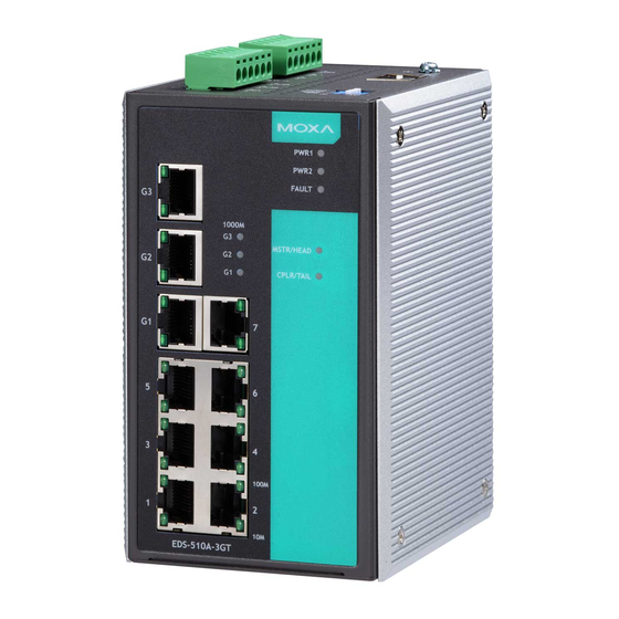
Package Checklist The EDS-510A is shipped with the following items. If any of these items are missing or damaged, please contact your customer service representative for assistance. • 1 EDS-510A EtherDevice Switch • Hardware Installation Guide (this guide) • CD-ROM with user’s manual and Windows utility •... - Page 3 Panel Views of EDS-510A 1. 1 to 7: 10/100BaseT(X) port 2. G1: EDS-510A-3GT 10/100/1000BaseT(X) port EDS-510A-1GT2SFP 10/100/1000BaseT(X) port EDS-510A-3SFP 1000BaseSX/LX/LHX/ZX port 3. G2: EDS-510A-3GT 10/100/1000BaseT(X) port EDS-510A-1GT2SFP 1000BaseSX/LX/LHX/ZX port EDS-510A-3SFP 1000BaseSX/LX/LHX/ZX port 4. G3: EDS-510A-3GT 10/100/1000BaseT(X) port EDS-510A-1GT2SFP 1000BaseSX/LX/LHX/ZX port EDS-510A-3SFP 1000BaseSX/LX/LHX/ZX port 5.
-
Page 4: Mounting Dimensions
Top Panel: 1. Ground screw 2. RS-232 console port 3. Heat dissipation orifices 4. DIP switches for Ring Master, Ring Coupler, and Turbo Ring 5. 6-pin terminal block for DI 1, DI 2, and PWR 2 6. 6-pin terminal block for PWR1, Relay 1, and Relay 2 Rear Panel: 1. -
Page 5: Din-Rail Mounting
DIN-Rail Mounting The aluminum DIN-Rail attachment plate should already be fixed to the back panel of the EDS-510A when you take it out of the box. If you need to reattach the DIN-Rail attachment plate to the EDS-510A, make sure the stiff metal spring is situated towards the top, as shown by the following figures. -
Page 6: Atex Information
STEP 3—Once the screws are fixed to the wall, insert the four screw heads through the wide parts of the keyhole-shaped apertures, and then slide the EDS-510A downwards, as indicated in the figure at the right. Tighten the four screws for more stability. - Page 7 ATTENTION Safety First! Be sure to disconnect the power cord before installing and/or wiring your Moxa EtherDevice Switch. Calculate the maximum possible current in each power wire and common wire. Observe all electrical codes dictating the maximum current allowable for each wire size. If the current goes above the maximum ratings, the wiring could overheat, causing serious damage to your equipment.
-
Page 8: Wiring The Relay Contact
Wiring the Relay Contact The EDS-510A has two sets of relay outputs—relay 1 and relay 2. Each relay contact uses two contacts of the terminal block on the EDS-510A’s top panel. Refer to the next section for detailed instructions on how to connect the wires to the terminal block connector, and how to attach the terminal block connector to the terminal block receptor. -
Page 9: Wiring The Digital Inputs
Wiring the Digital Inputs The EDS-510A has two sets of digital inputs, DI 1 and DI 2. Each DI consists of two contacts of the 6-pin terminal block connector on the EDS-510A’s top panel, which are used for the two DC inputs. The top and front views of one of the terminal block connectors are shown here. -
Page 10: 10/100Baset(X) Ethernet Port Connection
RS-232 Connection The EDS-510A has one RS-232 (10-pin RJ45) console port, located on the top panel. Use either an RJ45-to-DB9 (see the cable following wiring diagrams) to connect the EDS-510A’s console port to your PC’s COM port. You may then use a console terminal program, such as Moxa PComm Terminal Emulator, to access the EDS-510A’s console configuration utility. - Page 11 10/100Base T(x) RJ45 Pinouts MDI Port Pinouts MDI-X Port Pinouts 8-pin RJ45 Signal Signal RJ45 (8-pin) to RJ45 (8-pin) Straight-through Cable Wiring RJ45 (8-pin) to RJ45 (8-pin) Cross-over Cable Wiring 1000BaseT Ethernet Port Connection 1000BaseT data is transmitted on differential TRD+/- signal pairs over copper wires.
-
Page 12: Turbo Ring Dip Switch Settings
1000BaseSFP (mini-GBIC) Fiber Port The gigabit Ethernet ports on the EDS-510A-1GT2SFP and EDS-510A-3SFP are 1000BaseSFP Fiber ports, which require using the gigabit mini-GBIC fiber transceivers to work properly. Moxa provides completed transceiver models for different distance requirement. Please refer to Specifications section for more optical fiber information. The concept behind the LC port and cable is quite straightforward. - Page 13 EDS-510A Series DIP Switches The default setting for each DIP Switch is OFF. The following table explains the effect of setting the DIP Switch to the ON position. “Turbo Ring” DIP Switch Settings DIP 1 DIP 2 DIP 3 DIP 4 Reserved for ON: Enables this ON: Enables the...
-
Page 14: Led Indicators
LED Indicators The front panel of the Moxa EDS-510A contains several LED indicators. The function of each LED is described in the following table: Color State Description Power is being supplied to power input PWR1 AMBER Power is not being supplied to power input P1. -
Page 15: Specifications
Specifications Technology Standards IEEE802.3, 802.3u, 802.3x, 802.1D, 802.1w, 802.1Q, 802.1p, 802.1X, 802.3ad, 802.3z Protocols IGMPv1/v2, GMRP, GVRP, SNMPv1/v2c/v3, DHCP Server/Client, BootP, TFTP, SNTP, SMTP, RARP, RMON, HTTP, HTTPS, Telnet, Syslog, DHCP Option 66/67/82, SSH, SNMP Inform, Modbus/TCP, LLDP, IEEE 1588 PTP, IPv6 MIB-II, Ethernet-like MIB, P-BRIDGE MIB, Q-BRIDGE MIB, Bridge MIB, RSTP MIB, RMON MIB Group 1,2,3,9... - Page 16 1310nm 1550nm 1310nm 1550nm 1310nm 1550nm Wavelength 1550nm 1310nm 1550nm 1310nm 1550nm 1310nm Max. Tx -3 dBm -3 dBm -2 dBm -2 dBm +2 dBm +2 dBm Min. Tx -9 dBm -9 dBm -8 dBm -8 dBm -3 dBm -3 dBm -21 dBm -21 dBm -23 dBm -23 dBm Sensitivity...
- Page 17 Technical Support Contact Information www.moxa.com/support Moxa Americas: Moxa China (Shanghai office): Toll-free: 1-888-669-2872 Toll-free: 800-820-5036 Tel: 1-714-528-6777 Tel: +86-21-5258-9955 Fax: 1-714-528-6778 Fax: +86-21-5258-5505 Moxa Europe: Moxa Asia-Pacific: Tel: +49-89-3 70 03 99-0 Tel: +886-2-8919-1230 Fax: +49-89-3 70 03 99-99 Fax: +886-2-8919-1231 - 17 -...
Need help?
Do you have a question about the EtherDevice EDS-510A-3GT and is the answer not in the manual?
Questions and answers