Table of Contents
Advertisement
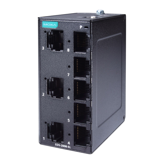
EDS-2008-EL/ELP Series
Quick Installation Guide
Moxa Americas:
Toll-free: 1-888-669-2872
Tel:
1-714-528-6777
Fax:
1-714-528-6778
Moxa Europe:
Tel:
+49-89-3 70 03 99-0
Fax:
+49-89-3 70 03 99-99
Moxa India:
Tel:
+91-80-4172-9088
Fax:
+91-80-4132-1045
Moxa EtherDevice Switch
Version 1.0, October 2019
Technical Support Contact Information
www.moxa.com/support
2019 Moxa Inc. All rights reserved.
Moxa China (Shanghai office):
Toll-free: 800-820-5036
Tel:
+86-21-5258-9955
Fax:
+86-21-5258-5505
Moxa Asia-Pacific:
Tel:
+886-2-8919-1230
Fax:
+886-2-8919-1231
P/N: 1802020080010
*1802020080010*
Advertisement
Table of Contents

Related Manuals for Moxa Technologies EDS-2008-EL Series


Summary of Contents for Moxa Technologies EDS-2008-EL Series
- Page 1 EDS-2008-EL/ELP Series Quick Installation Guide Moxa EtherDevice Switch Version 1.0, October 2019 Technical Support Contact Information www.moxa.com/support Moxa Americas: Moxa China (Shanghai office): Toll-free: 1-888-669-2872 Toll-free: 800-820-5036 Tel: 1-714-528-6777 Tel: +86-21-5258-9955 Fax: 1-714-528-6778 Fax: +86-21-5258-5505 Moxa Europe: Moxa Asia-Pacific: Tel: +49-89-3 70 03 99-0 Tel: +886-2-8919-1230...
-
Page 2: Package Checklist
Overview The EDS-2008-EL/ELP Series has an 8-port combination to simplify network expansion. There are two housing types available for the user to select depending on the requirements of their application. The ELP has a plastic housing and the EL has a metal housing. The compact switches provide a cost-effective solution for your industrial Ethernet connection requirements. - Page 3 Features High Performance Network Switching Technology • 10/100BaseT(X) auto-negotiation speed, full/half duplex mode, auto MDI/MDI-X connection, and 100BaseFX for fiber port models. • IEEE 802.3 for 10BaseT, IEEE 802.3u for 100BaseT(X). • IEEE 802.1p for Quality of Service (QoS) traffic prioritized function. •...
- Page 4 Panel Layout of EDS-2008-EL/EDS-2008-ELP 1. Chassis ground screw 2. Terminal block for power input 3. DIP switch 4. Power LED 5. 10/100 BaseT(X) Port 6. 10/100 BaseT(X) Port LED 7. Port number 8. Model name - 4 -...
- Page 5 Panel Layout of EDS-2008-EL-M-ST/ EDS-2008-EL-M-SC 1. Chassis ground screw 2. Terminal block for power input 3. DIP switch 4. Power LED 5. 10/100 BaseT(X) Port 6. 10/100 BaseT(X) Port LED 7. Port number 8. 10/100 BaseFX Multi-mode ST Port (only for ST models) 9.
-
Page 6: Mounting Dimensions
Mounting Dimensions EDS-2008-EL Series EDS-2008-ELP Series - 6 -... - Page 7 EDS-2008-EL-M-ST Series EDS-2008-EL-M-SC Series - 7 -...
-
Page 8: Din Rail Mounting
DIN-rail Mounting When shipped, the DIN-rail mounting kit is fixed to the back panel of the EDS. Mount the EDS on the corrosion-free mounting rail that adheres to the EN 60715 standard. Suggested Installation Method STEP 1: Insert the upper lip of the DIN- rail kit into the mounting rail. -
Page 9: Wall Mounting (Optional)
Wall Mounting (optional) For some applications, you will find it convenient to mount EDS on the wall, as illustrated below. There are two options for installation: The first option is to hook the EDS DIN-rail latch on the opening of the wall mount kit (see picture above) and then mount the wall-mount kit on the wall with screws. -
Page 10: Wiring Requirements
Wiring Requirements WARNING Do not disconnect modules or wires unless the power supply has been switched off or the area is known to be non- hazardous. The devices may only be connected to the supply voltage shown on the type plate. The devices are designed for operation with a Safety Extra-Low Voltage. -
Page 11: Wiring The Power Input
ATTENTION This product is intended to be mounted to a well-grounded mounting surface, such as a metal panel. Wiring the Power Input The top two contacts and the bottom two contacts of the 2 or 3 contact terminal block connector on the EDS’s top panel are used for the EDS’s two DC inputs. -
Page 12: 10/100Baset(X) Ethernet Port Connection
10/100BaseT(X) Ethernet Port Connection The 10/100BaseT(X) ports located on the EDS’s front panel are used to connect to Ethernet-enabled devices. Below we show pinouts for both MDI (NIC-type) ports and MDI-X (HUB/Switch-type) ports, and also show cable wiring diagrams for straight-through and cross-over Ethernet cables. -
Page 13: Dip Switch Settings
SC-port Pinouts SC-port to SC-port Cable Wiring ST-port Pinouts ST-port to ST-port Cable Wiring ATTENTION This is a Class 1 Laser/LED product. To prevent damage to your eyes, do not stare directly into the laser beam. DIP Switch Settings DIP Switch Setting Description Quality of... -
Page 14: Led Indicators
LED Indicators The front panel of the Moxa EtherDevice Switch contains several LED indicators. The function of each LED is described in the table below. Color State Description Power is being supplied to power input PWR. Amber Power is not being supplied to power input PWR. -
Page 15: Switching And Address Learning
Switching and Address Learning The Moxa EDS has an address table that can hold up to 8,000 node addresses, which makes it suitable for use with large networks. The address tables are self-learning, so that as nodes are added or removed, or moved from one segment to another, EDS automatically keeps up with new node locations. - Page 16 Reverse Polarity Present Protection Mechanical Casing IP40 protection, metal housing for EL Series; plastic housing for ELP Series Dimensions EDS-2008-EL/ELP: (W x H x D) 36 x 81 x 65 mm (1.4 x 3.19 x 2.56 in) EDS-2008-EL-M-ST: 36 x 81 x 70.9 mm (1.4 x 3.19 x 2.79 in) EDS-2008-EL-M-SC: 36 x 81 x 67.9 mm (1.4 x 3.19 x 2.67 in) Weight...
Need help?
Do you have a question about the EDS-2008-EL Series and is the answer not in the manual?
Questions and answers