Table of Contents
Advertisement
Advertisement
Table of Contents

Related Manuals for Kontron KTD-N0850-B


Summary of Contents for Kontron KTD-N0850-B
- Page 1 KTQM77/mITX KTQM77/mITX Users Guide KTD-N0850-B If it’s embedded, it’s Kontron...
-
Page 2: Document Revision History
Copyright 2011, KONTRON Technology A/S, ALL RIGHTS RESERVED. No part of this document may be reproduced or transmitted in any form or by any means, electronically or mechanically, for any purpose, without the express written permission of KONTRON Technology A/S. Trademark Acknowledgement: Brand and product names are trademarks or registered trademarks of their respective owners. - Page 3 KONTRON Technology warrants its products to be free from defects in material and workmanship during the warranty period. If a product proves to be defective in material or workmanship during the warranty period, KONTRON Technology will, at its sole option, repair or replace the product with a similar product.
-
Page 4: Table Of Contents
KTD-N0850-B Page 4 Contents Contents Introduction ..................... 7 Installation procedure ................ 8 Installing the board .......................... 8 Requirement according to IEC60950 ....................9 System Specification ................ 10 Component main data ........................10 System overview ..........................14 Processor Support Table ........................16 System Memory support ........................ - Page 5 KTD-N0850-B Page 5 USB Connector 6/7 ........................41 6.6.1 USB Connector 8/9 (USB8/9) (J10) ....................41 6.6.2 USB Connector 10/11 (USB10/11) (J11) ..................42 6.6.3 USB Connector 12/13 (USB12/13) (J12) ..................42 6.6.4 Firewire/IEEE1394 connectors (J13,J14) ................... 43 IEEE1394 connector (IEEE1394_0) (J14) ..................43 6.7.1...
- Page 6 KTD-N0850-B Page 6 10.2.18 Advanced - CPU PPM Configuration....................100 Chipset ............................102 10.3 10.3.1 PCH-IO Configuration ........................103 10.3.2 System Agent (SA) Configuration ....................109 Boot ............................126 10.4 10.4.1 CSM parameters ........................... 128 Security ............................129 10.5 10.5.1 Image Execution Policy ........................ 130 Save &...
-
Page 7: Introduction
Page 7 Introduction Introduction This manual describes the KTQM77/mITX board made by KONTRON Technology A/S. The boards will also be denoted KTQM77. The KTQM77 board is based on the QM77 chipset, support 3 generation Intel® i7 -, i5 -, i3 2Core and 4Core mobile processors. -
Page 8: Installation Procedure
1 Installation procedure 1.1 Installing the board To get the board running, follow these steps. If the board shipped from KONTRON has already components like RAM, CPU and cooler mounted, then relevant steps below, can be skipped. 1. Turn off the PSU (Power Supply Unit) Warning: Turn off PSU (Power Supply Unit) completely (no mains power connected to the PSU) or leave the Power Connectors unconnected while configuring the board. -
Page 9: Requirement According To Iec60950
Installation procedure KTD-N0850-B Page 9 1.2 Requirement according to IEC60950 Users of KTQM77 should take care when designing chassis interface connectors in order to fulfil the IEC60950 standard: When an interface/connector has a VCC (or other power) pin, which is directly connected to a power... -
Page 10: System Specification
KTD-N0850-B Page 10 System Specification 2 System Specification 2.1 Component main data The table below summarizes the features of the KTQM77/mITX embedded motherboard. Form factor KTQM77/mITX: miniITX (170,18 mm by 170,18 mm) Processor Support the following 3 Generation Intel® Core™ (Ivy Bridge M) processors via Socket G2 (rPGA 988B ) ZIF Socket •... - Page 11 KTD-N0850-B Page 11 System Specification Video Intel ® i3, i5 & i7 3 Generation Mobile processors support Intel ® HD Graphics 4000. eDP (Embedded DisplayPort) directly from processor. Analogue VGA and digital display ports (DVI, 2x DP, LVDS) via the Mobile Intel ®...
- Page 12 Dispose of used batteries according to the manufacturer’s instructions. BIOS • Kontron Technology / AMI BIOS (EFI core version) • Support for ACPI 3.0 ( Advanced Configuration and Power Interface), Plug & Play Suspend (S1 mode)
- Page 13 -20°C – 70°C; lower limit of storage temperature is defined by specification restriction of on-board CR2032 battery. Board with battery has been verified for storage temperature down to -40°C by Kontron. 5% - 95% relative humidity (non-condensing) Electro Static Discharge (ESD) / Radiated Emissions (EMI): All Peripheral interfaces intended for connection to external equipment are ESD/ EMI protected.
-
Page 14: System Overview
KTD-N0850-B Page 14 System Specification 2.2 System overview The block diagram below shows the architecture and main components of the KTQM77. The key ® component on the board is the Intel QM77 (Panther Point) Mobile Express Chipset. Some components (PCI slots) are optional depending on board type. - Page 15 KTD-N0850-B Page 15 System Specification KTQM77/mITX Users Guide...
-
Page 16: Processor Support Table
CPU’s are indicated by text. Some processors in the list are distributed from Kontron, those CPU’s are marked by an * (asterisk). However please notice that this marking is only guide line and maybe not fully updated. Processor... -
Page 17: System Memory Support
(worst-case) ambient operating temperature and the actual load of processor. The Kontron PN 1044-9447 is “Active Cooler for KTQM67/KTQM77” capable of being used for processors (fully loaded) having Thermal Guideline up to 45W @ 60ºC ambient temperature. -
Page 18: Ktqm77 Graphics Subsystem
KTD-N0850-B Page 18 System Specification 2.5 KTQM77 Graphics Subsystem The KTQM77 equipped with Intel ® i3, i5 or i7 processor, supports Intel ® HD Graphics 4000. All KTQM77 versions support eDP (Embedded DisplayPort) directly from processor, and analogue VGA and digital display ports (DVI, 2x DP, LVDS) via the Mobile Intel ® QM77 Chipset. The Analogue VGA and DVI-D are sharing the DVI-I connector. -
Page 19: Power Consumption
KTD-N0850-B Page 19 System Specification 2.6 Power Consumption In order to ensure safe operation of the board, the ATX12V power supply must monitor the supply voltage and shut down if the supplies are out of range – refer to the hardware manual for the actual power supply specification. - Page 20 KTD-N0850-B Page 20 System Specification The principal test system and test equipment used Tektronix TDS5104B KTQM67 Tektronix TCPA300 Tektronix TCP312 ATX supplies Fluke 289 Current Fluke 179 Tektronix TDS5104B Probe ATX rail switch Note: Power consumption of PSU (power loss), Monitor and HDD are not included.
- Page 21 KTD-N0850-B Page 21 System Specification a) Low Power Setup KTQM77/mITX ATX+12V PSU DOS Idle, Mean, No external load Current draw Power consumption Supply +12V 0,140 1,680 +12V P4 1,222 14,664 0,411 2,055 +3V3 0,557 1,838 -12V 0,035 0,42 5VSB 0,007...
- Page 22 KTD-N0850-B Page 22 System Specification b) Low Power Setup KTQM77/mITX +12V only PSU DOS Idle, Mean, No external load Current draw Power consumption Supply +12V P4 1,721 20,652 Total 20,7 Windows 7, mean 3DMARK2005 ( first scene ) & BiT 6...
- Page 23 KTD-N0850-B Page 23 System Specification c) High Power Setup KTQM77/mITX ATX+12V PSU DOS Idle, Mean, No external load Current draw Power consumption Supply +12V 0,932 11,184 +12V P4 1,102 13,224 0,452 2,260 +3V3 0,553 1,825 -12V 0,036 0,432 5VSB 0,007...
- Page 24 System Specification KTD-N0850-B Page 24 d) High Power Setup KTQM77/mITX +12V only PSU DOS Idle, Mean, No external load Current draw Power consumption Supply +12V P4 2,499 29,988 Total 30,0 Windows 7, mean 3DMARK2005 ( first scene ) & BiT 6...
-
Page 25: Connector Locations
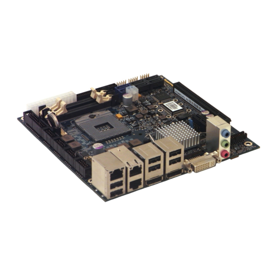
KTD-N0850-B Page 25 Connector Location 3 Connector Locations 3.1 KTQM77/mITX – frontside Sata1 Sata4 Sata2 mPCIe (* Sata0 Sata5 Sata3 USB11 (see note below) USB10 USB13 USB9 USB12 USB8 FEATURE ATX/ BTXPWR System Temperature ATX+12V Sensor( R916) DDR3 Slot 1... -
Page 26: Ktqm77/Mitx - Io Bracket Area
KTD-N0850-B Page 26 Connector Location 3.2 KTQM77/mITX – IO Bracket area ETH1 USB1 USB3 ETH2 USB5 USB0 USB2 ETH3 USB4 DVI-I Audio 3.3 KTQM77/mITX - backside PCB no. XDP-CPU (*) mPCIe1 XDP-PCH (*) below mPCIe1 mPCIe0 LPT (*) (*) The XDP and LPT connectors are not supported and not mounted in volume production. -
Page 27: Connector Definitions
KTD-N0850-B Page 27 Connector Definitions 4 Connector Definitions The following sections provide pin definitions and detailed description of all on-board connectors. The connector definitions follow the following notation: Column Description name Shows the pin-numbers in the connector. The graphical layout of the connector definition tables is made similar to the physical connectors. -
Page 28: Io-Area Connectors
KTD-N0850-B Page 28 IO-Area Connectors 5 IO-Area Connectors 5.1 Display connectors (IO Area) The KTQM77 provides one on-board DVI-I port (both digital and analogue), two on-board DP’s (DisplayPort), one on-board eDP (Embedded DisplayPort) and one on-board LVDS panel interface. Two graphic pipes are supported;... -
Page 29: Dp Connectors (Dp0/Dp1) (J40/J39)
KTD-N0850-B Page 29 IO-Area Connectors 5.1.2 DP Connectors (DP0/DP1) (J40/J39) The DP (DisplayPort) connectors are based on standard DP type Foxconn 3VD51203-H7JJ-7H or similar. Signal Description Type Note Lane 0 (p) LVDS Lane 0 (n) LVDS Lane 1 (p) LVDS... -
Page 30: Ethernet Connectors
KTD-N0850-B Page 30 IO-Area Connectors 5.2 Ethernet Connectors The KTQM77 supports three channels of 10/100/1000Mb Ethernet, one (ETH1) is based on Intel® Lewisville 82579LM Gigabit PHY with AMT 7.0 support and the two other controllers (ETHER2 & ETHER3) are based on Intel® Hartwell 82574L PCI Express controller. -
Page 31: Usb Connectors (Io Area)
KTD-N0850-B Page 31 IO-Area Connectors 5.3 USB Connectors (IO Area) The KTQM77 board contains two EHCI (Enhanced Host Controller Interface) and one XHCI (Extensible Host Controller Interface). The two EHCI controllers, EHCI1 and EHCI2, supports up to fourteen USB 2.0 ports allowing data transfers up to 480Mb/s. The XHCI controller supports four USB 3.0 ports allowing data transfers up to 5Gb/s. -
Page 32: Usb Connector 0/1 (Usb0/1)
KTD-N0850-B Page 32 IO-Area Connectors 5.3.1 USB Connector 0/1 (USB0/1) USB Ports 0 and 1 are mounted together with DP0 port and supports USB3.0/USB2.0. Note Type Signal Signal Type Note USB1- USB1+ 5V/SB5V RX1- TX1+ RX1+ TX1- USB0- USB0+ 5V/SB5V... -
Page 33: Usb Connector 2/3 (Usb2/3)
KTD-N0850-B Page 33 IO-Area Connectors 5.3.2 USB Connector 2/3 (USB2/3) USB Ports 2 and 3 are mounted together with DP1 port and supports USB3.0/USB2.0. Note Type Signal Signal Type Note USB3- USB3+ 5V/SB5V RX3- TX3+ RX3+ TX3- USB2- USB2+ 5V/SB5V... -
Page 34: Audio Connector (Io Area)
KTD-N0850-B Page 34 IO-Area Connectors 5.4 Audio Connector (IO Area) The on-board Audio circuit implements 7.1+2 Channel High Definition Audio with UAA (Universal Audio Architecture), featuring five 24-bit stereo DACs and three 20-bit stereo ADCs. The Following Audio connector is available in IO Area. -
Page 35: Internal Connectors
KTD-N0850-B Page 35 Internal Connectors 6 Internal Connectors 6.1 Power Connector (ATX/BTXPWR) The KTQM77 boards are designed to be supplied from a standard ATX (or BTX) power supply. Alternatively supplied by single +12V +/-5% (mITX version only). Use of BTX supply is not required for operation, but may be required to drive high-power PCIe cards. -
Page 36: Fan Connectors (Fan_Cpu) (J28) And (Fan_Sys) (J29)
KTD-N0850-B Page 36 Internal Connectors 6.2 Fan Connectors (FAN_CPU) (J28) and (FAN_SYS) (J29) The FAN_CPU is used for the connection of the FAN for the CPU. The FAN_SYS can be used to power, control and monitor a fan for chassis ventilation etc. -
Page 37: Ps/2 Keyboard And Mouse Connector (Kbdmse) (J27)
KTD-N0850-B Page 37 Internal Connectors 6.3 PS/2 Keyboard and Mouse connector (KBDMSE) (J27) Attachment of a PS/2 keyboard/mouse can be done through the pinrow connector KBDMSE (J27). Both interfaces utilize open-drain signalling with on-board pull-up. The PS/2 mouse and keyboard is supplied from SB5V when in standby mode in order to enable keyboard or mouse activity to bring the system out from power saving states. -
Page 38: Display Connectors (Internal)
KTD-N0850-B Page 38 Internal Connectors 6.4 Display connectors (Internal) The KTQM77 provides internal display connectors: one on-board eDP (Embedded DisplayPort) and one on-board LVDS panel interface. For IO Area Display Connectors (DVI-I and two DP’s), see earlier section. Two graphic pipes are supported; meaning that up to two independent displays can be implemented using any two of display connectors (IO Area - and Internal connectors) with the exception of the combination eDP + LVDS. -
Page 39: Lvds Flat Panel Connector (Lvds) (J20)
KTD-N0850-B Page 39 Internal Connectors 6.4.2 LVDS Flat Panel Connector (LVDS) (J20) Two graphic pipes are supported; meaning that up to two independent displays can be implemented using any two of display connectors (IO Area - and Internal connectors) with the exception of the combination eDP + LVDS. -
Page 40: Sata (Serial Ata) Disk Interface (J21 - J26)
KTD-N0850-B Page 40 Internal Connectors 6.5 SATA (Serial ATA) Disk interface (J21 – J26) The KTQM77 has an integrated SATA Host controller (PCH in the QM77 chipset) that supports independent DMA operation on six ports. One device can be installed on each port for a maximum of six SATA devices. -
Page 41: Usb Connectors (Usb)
KTD-N0850-B Page 41 Internal Connectors 6.6 USB Connectors (USB) The KTQM77 board contains two EHCI (Enhanced Host Controller Interface) host controllers (EHCI1 and EHCI2) that support up to fourteen USB 2.0 ports allowing data transfers up to 480Mb/s. Legacy Keyboard/Mouse and wakeup from sleep states are supported. Over-current detection on all fourteen USB ports is supported. -
Page 42: Usb Connector 10/11 (Usb10/11) (J11)
KTD-N0850-B Page 42 Internal Connectors 6.6.3 USB Connector 10/11 (USB10/11) (J11) USB Ports 10 and 11 are supplied on the internal USB10/11 pinrow connector J11. Note Type Signal Signal Type Note PWR 5V/SB5V 5V/SB5V PWR USB10- USB11- USB10+ USB11+ 9 10... -
Page 43: Firewire/Ieee1394 Connectors (J13,J14)
KTD-N0850-B Page 43 Internal Connectors 6.7 Firewire/IEEE1394 connectors (J13,J14) The KTQM77 support two IEEE Std 1394a-2000 fully compliant ports at 100M bits/s, 200M bits/s and 400M bits/s. 6.7.1 IEEE1394 connector (IEEE1394_0) (J14) Pull Pull Note Ioh/Iol Type Signal PIN Signal Type Ioh/Iol... -
Page 44: Serial Com1 - Com4 Ports (J15, J16, J17, J18)
KTD-N0850-B Page 44 Internal Connectors 6.8 Serial COM1 – COM4 Ports (J15, J16, J17, J18) Four RS232 serial ports are available on the KTQM77. The typical definition of the signals in the COM ports is as follows: Signal Description Transmitted Data, sends data to the communications link. The signal is set to the marking state (-12V) on hardware reset when the transmitter is empty or when loop mode operation is initiated. -
Page 45: Audio Connectors
KTD-N0850-B Page 45 Internal Connectors 6.9 Audio Connectors The on-board Audio circuit implements 7.1+2 Channel High Definition Audio with UAA (Universal Audio Architecture), featuring five 24-bit stereo DACs and three 20-bit stereo ADCs. The following Audio connectors are available as Internal connectors. -
Page 46: Audio Header Connector (Audio_Head) (J31)
KTD-N0850-B Page 46 Internal Connectors 6.9.3 Audio Header Connector (AUDIO_HEAD) (J31) Note Type Signal Signal Type Note LFE-OUT CEN-OUT AAGND AAGND FRONT-OUT-L FRONT-OUT-R AAGND AAGND REAR-OUT-L 9 10 REAR-OUT-R SIDE-OUT-L 11 12 SIDE-OUT-R AAGND 13 14 AAGND MIC1-L 15 16... -
Page 47: Front Panel Connector (Frontpnl) (J19)
KTD-N0850-B Page 47 Internal Connectors 6.9.4 Front Panel Connector (FRONTPNL) (J19) Pull Ioh/ Ioh/ Pull Note Type Signal Signal Type Note PWR USB6/7_5V USB6/7_5V USB6- USB7- USB6+ USB7+ 9 10 LINE2-L 11 12 25/25mA SATA_LED# 13 14 SUS_LED 15 16... -
Page 48: Feature Connector (Feature) (J30)
KTD-N0850-B Page 48 Internal Connectors 6.10 Feature Connector (FEATURE) (J30) Pull Pull Note Ioh/Iol Type Signal Signal Type Ioh/Iol Note CASE_OPEN# SMBC /4mA 10K/ 25/25mA SMBD /4mA 10K/ 25/25mA PWR_OK EXT_BAT PWR FAN3OUT FAN3IN SB3V3 9 10 SB5V GPIO0 11 12... - Page 49 KTD-N0850-B Page 49 Internal Connectors Signal Description CASE OPEN, used to detect if the system case has been opened. This signal’s status CASE_OPEN# is readable, so it may be used like a GPI when the Intruder switch is not required.
- Page 50 KTD-N0850-B Page 50 Internal Connectors GPIO in more details. The GPIO’s are controlled via the ITE IT8516F Embedded Controller. Each GPIO has 100pF to ground, clamping Diode to 3V3 and has multiplexed functionality. Some pins can be DAC (Digital to Analogue...
-
Page 51: Load Default Bios Settings" Jumper (J37)
Internal Connectors KTD-N0850-B Page 51 6.11 “Load Default BIOS Settings” Jumper (J37) The “Load Default BIOS Settings” Jumper (J37) can be used to recover from incorrect BIOS settings. As an example, incorrect BIOS settings coursing no display to turn on can be erased by the Jumper. -
Page 52: Spi Recover Jumper (J4)
KTD-N0850-B Page 52 Internal Connectors 6.12 SPI Recover Jumper (J4) The SPI Recover Jumper is used to select BIOS Recovery Flash instead of BIOS Default Flash. Normally SPI Recovery Jumper is not installed and board boots on the BIOS Default Flash. Only in case the Default BIOS gets corrupted (board do not boot) follow the procedure: 1. -
Page 53: Xdp-Cpu (Debug Port For Cpu) (J32)
KTD-N0850-B Page 53 Internal Connectors 6.14 XDP-CPU (Debug Port for CPU) (J32) The XDP-CPU (Intel Debug Port for CPU) connector is not mounted and not supported. XDP connector layout (pads) is located on the backside of PCB and is prepared for the Molex 52435-2671 (or 52435- 2672). -
Page 54: Xdp-Pch (Debug Port For Chipset) (J33)
KTD-N0850-B Page 54 Internal Connectors 6.15 XDP-PCH (Debug Port for Chipset) (J33) The XDP-PCH (Intel Debug Port for Chipset) connector is not mounted and not supported. XDP-PCH connector layout (pads) is located on the backside of PCB (below J35 connector on mITX version) and is prepared for the Molex 52435-2671 (or 52435-2672). -
Page 55: Slot Connectors (Pcie, Minipcie, Pci)
KTD-N0850-B Page 55 Slot Connectors 7 Slot Connectors (PCIe, miniPCIe, PCI) 7.1 PCIe Connectors All members of the KTQM77 family supports one (x16) (16-lane) PCI Express port, one x1 PCI Express port and two miniPCI Express ports. The 16-lane (x16) PCI Express (PCIe 2.0 and PCIe 3.0) port can be used for external PCI Express cards inclusive graphics card. - Page 56 KTD-N0850-B Page 56 Slot Connectors PEG_RXN[4] PEG_TXP[5] PEG_TXN[5] PEG_RXP[5] PEG_RXN[5] PEG_TXP[6] PEG_TXN[6] PEG_RXP[6] PEG_RXN[6] PEG_TXP[7] PEG_TXN[7] PEG_RXP[7] CLKREQ PEG_RXN[7] PEG_TXP[8] PEG_TXN[8] PEG_RXP[8] PEG_RXN[8] PEG_TXP[9] PEG_TXN[9] PEG_RXP[9] PEG_RXN[9] PEG_TXP[10] PEG_TXN[10] PEG_RXP[10] PEG_RXN[10] PEG_TXP[11] PEG_TXN[11] PEG_RXP[11] PEG_RXN[11] PEG_TXP[12] PEG_TXN[12] PEG_RXP[12] PEG_RXN[12] PEG_TXP[13]...
-
Page 57: Minipci-Express Mpcie0 (J34)
KTD-N0850-B Page 57 Slot Connectors 7.1.2 miniPCI-Express mPCIe0 (J34) The miniPCI Express port mPCIe0 is located on the backside. Beside miniPCIe cards the mPCIe0 also supports mSATA SSD cards. Note: no USB signals are available. Note Type Signal Signal Type... -
Page 58: Minipci-Express Mpcie1 (J35)
KTD-N0850-B Page 58 Slot Connectors 7.1.3 miniPCI-Express mPCIe1 (J35) The miniPCI Express port mPCIe1 is located on the backside. Note: no USB or mSATA signals are available. Note Type Signal Signal Type Note WAKE# +3V3 +1.5V CLKREQ# PCIE_mini CLK# PCIE_mini CLK... -
Page 59: Pci-Express X1 Connector (Pcie X1) (J36)
KTD-N0850-B Page 59 Slot Connectors 7.1.4 PCI-Express x1 Connector (PCIe x1) (J36) Connector Definitions The KTQM77/mITX supports one PCIe x1. Note Type Signal Signal Type Note +12V +12V +12V +12V +12V SMB_CLK SMB_DATA +3V3 JTAG_TEST# +3V3 3V3 Dual B10 A10... -
Page 60: On-Board - & Mating Connector Types
Onboard/mating connector KTD-N0850-B Page 60 8 On-board - & mating connector types The Mating connectors / Cables are connectors or cable kits which are fitting the On-board connector. The highlighted cable kits are included in the “KTQM67 Cable & Driver Kit” PN 826598, in different quantities depending on type of connector. -
Page 61: System Resources
System Resources KTD-N0850-B Page 61 9 System Resources 9.1 Memory Map Address (hex) Size (hex) Description Intel® 82802 Firmware Hub Device 0xFF000000 0xFFFFFFFF 1000000 Motherboard resources 0xFEE00000 0xFEEFFFFF 100000 Motherboard resources 0xFED90000 0xFED93FFF 4000 Motherboard resources 0xFED45000 0xFED8FFFF 4B000 Motherboard resources... -
Page 62: Interrupt Usage
KTD-N0850-B Page 62 System Resources 9.3 Interrupt Usage Notes IRQ0 IRQ1 IRQ2 IRQ3 IRQ4 IRQ5 IRQ6 IRQ7 IRQ8 IRQ9 IRQ10 IRQ11 IRQ12 IRQ13 IRQ14 IRQ15 IRQ16 IRQ17 IRQ18 IRQ19 IRQ20 IRQ21 IRQ22 IRQ23 IRQ24 IRQ25 IRQ26 KTQM77/mITX Users Guide... -
Page 63: Io Map
KTD-N0850-B Page 63 System Resources 9.4 IO Map Address range (hex) Size (hex) Description 0x0000FFFF 0x0000FFFF Motherboard resources 0x0000F0D0 0x0000F0D7 Intel® 7 port SATA AHCI – 1E03 0x0000F0C0 0x0000F0C3 Intel® 7 port SATA AHCI – 1E03 0x0000F0B0 0x0000F0B7 Intel® 7 port SATA AHCI – 1E03... -
Page 64: Bios
KTD-N0850-B Page 64 BIOS - Main 10 BIOS The BIOS Setup is used to view and configure BIOS settings for the board. The BIOS Setup is accessed by pressing the <Del> -key after the Power-On Self-Test (POST) memory test begins and before the operating system boot begins. -
Page 65: Advanced
KTD-N0850-B Page 65 BIOS - Advanced 10.2 Advanced Aptio Setup Utility – Copyright © 2012 American Megatrends, Inc. Main Advanced Chipset Boot Security Save & Exit PCI Subsystem Settings PCI, PCI-X and PCI Express ► ACPI Settings Settings. ► Trusted Computing ►... -
Page 66: Advanced - Pci Subsystem Settings
KTD-N0850-B Page 66 BIOS - Advanced 10.2.1 Advanced - PCI Subsystem Settings Aptio Setup Utility – Copyright © 2012 American Megatrends, Inc. Advanced PCI Bus Driver Version V 2.05.02 Enables or Disables 64bit capable Devices to be Decoded PCI 64bit Resources Handling... - Page 67 KTD-N0850-B Page 67 BIOS - Advanced 10.2.1.1 PCI Express Settings Aptio Setup Utility – Copyright © 2012 American Megatrends, Inc. Advanced PCI Express Link Register Settings Set the ASPM Level: Force L0s - Force all links to L0s State: ASPM Support [Disabled] Auto –...
- Page 68 KTD-N0850-B Page 68 BIOS - Advanced 10.2.1.2 PCI Express GEN 2 Settings Aptio Setup Utility – Copyright © 2012 American Megatrends, Inc. Advanced PCI Express GEN2 Link Register Settings If supported by hardware and set to ‘Force to 2.5GT/s’ for...
-
Page 69: Advanced - Apci Settings
KTD-N0850-B Page 69 BIOS - Advanced 10.2.2 Advanced - APCI Settings Aptio Setup Utility – Copyright © 2012 American Megatrends, Inc. Advanced ACPI Settings Enables or Disables BIOS APCI Auto Configuration. Enable ACPI Auto Configuration [Disabled] Enable Hibernation [Enabled] ACPI Sleep State [Both S1 and S3 ava…]... -
Page 70: Advanced - Trusted Computing
KTD-N0850-B Page 70 BIOS - Advanced 10.2.3 Advanced - Trusted Computing Aptio Setup Utility – Copyright © 2012 American Megatrends, Inc. Advanced Configuration Enables or Disables BIOS Security Device Support [Enable] support for security device. O.S. TPM State [Enabled] will not show Security Device. -
Page 71: Advanced - Cpu Configuration
KTD-N0850-B Page 71 BIOS - Advanced 10.2.4 Advanced - CPU Configuration Aptio Setup Utility – Copyright © 2012 American Megatrends, Inc. Advanced CPU Configuration Enabled for Windows XP and Linux (OS optimized for Hyper- Intel® Core™ i5-3610ME CPU @ 2.70GHz... - Page 72 BIOS - Advanced KTD-N0850-B Page 72 Notes: Intel HT Technology (Hyper Threading Technology) is a performance feature which allows one core on the processor to appear like 2 cores to the operating system. This doubles the execution resources available to the O/S, which potentially increases the performance of your overall system.
-
Page 73: Advanced - Sata Configuration
KTD-N0850-B Page 73 BIOS - Advanced 10.2.5 Advanced - SATA Configuration Aptio Setup Utility – Copyright © 2012 American Megatrends, Inc. Advanced SATA Controller(s) [Enabled] Enable or Disable SATA Device. SATA Mode Selection [ACHI] SATA Controller Speed [Gen3] Software Feature Mask Configuration ►... - Page 74 KTD-N0850-B Page 74 BIOS - Advanced 10.2.5.1 Software Feature Mask Configuration Aptio Setup Utility – Copyright © 2012 American Megatrends, Inc. Advanced RAID0 [Enabled] Enables or Disables RAID0 RAID1 [Enabled] feature. RAID10 [Enabled] RAID5 [Enabled] Intel Rapid Recovery Technology [Enabled]...
- Page 75 KTD-N0850-B Page 75 BIOS - Advanced Submenu Software Feature Mask Configuration description: Function Selection Description Disabled RAID0 Enable or disable RAID0 feature. Enabled Disabled RAID1 Enable or disable RAID1 feature. Enabled Disabled RAID10 Enable or disable RAID10 feature. Enabled Disabled RAID5 Enable or disable RAID5 feature.
- Page 76 KTD-N0850-B Page 76 BIOS - Advanced Remaining SATA Configuration menu description: Function Selection Description Disabled Port 0 Enable or Disable SATA Port. Enabled Disabled Hot Plug Designates this port as Hot Pluggable. Enabled Disabled External SATA External SATA Support. Enabled...
-
Page 77: Advanced - Intel Txt (Lt) Configuration
KTD-N0850-B Page 77 BIOS - Advanced 10.2.6 Advanced - Intel TXT (LT) Configuration Aptio Setup Utility – Copyright © 2012 American Megatrends, Inc. Advanced Intel Trusted Execution Technology Configuration Enables or Disables Intel ® TXT (LT) support. Intel TXT support only can be enabled/disabled if SMX is enabled. -
Page 78: Advanced - Amt Configuration
KTD-N0850-B Page 78 BIOS - Advanced 10.2.7 Advanced - AMT Configuration Aptio Setup Utility – Copyright © 2012 American Megatrends, Inc. Advanced Intel AMT [Disabled] Enable/Disable Intel ® Active BIOS Hotkey Pressed [Disabled] Management Technology BIOS MEBx Selection Screen [Disabled] Extension. - Page 79 KTD-N0850-B Page 79 BIOS - Advanced Function Selection Description Set timer to wait before sending AMT Wait Timer (Note1) 0 - 65535 (Note4) ASF_GET_BOOT_OPTIONS. Disabled Disable ME (Note1) Set ME to Soft Temporary Disabled. Enabled Disabled (Note1) Enable/Disabled Alert Specification Format.
-
Page 80: Advanced - Acoustic Management Configuration
KTD-N0850-B Page 80 BIOS - Advanced 10.2.8 Advanced - Acoustic Management Configuration Aptio Setup Utility – Copyright © 2012 American Megatrends, Inc. Advanced Acoustic Management Configuration Option to Enable or Disable Automatic Acoustic Automatic Acoustic Management [Disabled] Management Sata Port 0... -
Page 81: Advanced - Usb Configuration
KTD-N0850-B Page 81 BIOS - Advanced 10.2.9 Advanced - USB Configuration Aptio Setup Utility – Copyright © 2012 American Megatrends, Inc. Advanced USB Configuration Enables Legacy USB support. AUTO option disables legacy USB Devices: support if no USB devices are 2 Hubs connected. -
Page 82: Advanced - Smart Settings
KTD-N0850-B Page 82 BIOS - Advanced 10.2.10 Advanced - SMART Settings Aptio Setup Utility – Copyright © 2012 American Megatrends, Inc. Advanced SMART Settings Run SMART Self Test on all HDDs during POST. SMART Self Test [Disabled] →← : Select Screen ↑↓... -
Page 83: Advanced - Super Io Configuration
KTD-N0850-B Page 83 BIOS - Advanced 10.2.11 Advanced - Super IO Configuration Aptio Setup Utility – Copyright © 2012 American Megatrends, Inc. Advanced Super IO Configuration Set Parameters of Serial Port 1 (COMA) Super IO Chip IT8516F Serial Port 1 Configuration ►... - Page 84 KTD-N0850-B Page 84 BIOS - Advanced 10.2.11.1 Serial Port 1 Configuration Aptio Setup Utility – Copyright © 2012 American Megatrends, Inc. Advanced Serial Port 1 Configuration Enable or Disable Serial Port (COM) Serial Port [Enabled] Device Settings IO=3F8h; IRQ=4; Change Settings [Auto] →←...
- Page 85 KTD-N0850-B Page 85 BIOS - Advanced 10.2.11.2 Serial Port 2 Configuration Aptio Setup Utility – Copyright © 2012 American Megatrends, Inc. Advanced Serial Port 2 Configuration Enable or Disable Serial Port (COM) Serial Port [Enabled] Device Settings IO=2F8h; IRQ=3; Change Settings [Auto] →←...
- Page 86 KTD-N0850-B Page 86 BIOS - Advanced 10.2.11.3 Serial Port 3 Configuration Aptio Setup Utility – Copyright © 2012 American Megatrends, Inc. Advanced Serial Port 3 Configuration Enable or Disable Serial Port (COM) Serial Port [Enabled] Device Settings IO=3E8h; IRQ=7; Change Settings...
- Page 87 BIOS - Advanced KTD-N0850-B Page 87 10.2.11.4 Serial Port 4 Configuration Aptio Setup Utility – Copyright © 2012 American Megatrends, Inc. Advanced Serial Port 4 Configuration Enable or Disable Serial Port (COM) Serial Port [Enabled] Device Settings IO=2E8h; IRQ=10; Change Settings...
- Page 88 KTD-N0850-B Page 88 BIOS - Advanced 10.2.11.5 Parallel Port Configuration Note: Parallel Port is not available (connector not mounted). Aptio Setup Utility – Copyright © 2012 American Megatrends, Inc. Advanced Port Configuration Enable or Disable Parallel Port Parallel (LPT/LPTE) Parallel Port...
-
Page 89: Advanced - Voltage Monitor
KTD-N0850-B Page 89 BIOS - Advanced 10.2.12 Advanced - Voltage Monitor Aptio Setup Utility – Copyright © 2012 American Megatrends, Inc. Advanced Voltage Monitor VCore : 0.968 V 1.05 : 1.064 V : 1.512 V : 3.392 V 3.3SB : 3.392 V : 5.188 V... -
Page 90: Advanced - Hardware Health Configuration
KTD-N0850-B Page 90 BIOS - Advanced 10.2.13 Advanced - Hardware Health Configuration Aptio Setup Utility – Copyright © 2012 American Megatrends, Inc. Advanced Hardware Health Configuration Disabled = Full speed. System Temperature : 30ºC/86ºF Thermal: does regulate fan CPU Temperature : 49.10ºC/120ºF... - Page 91 KTD-N0850-B Page 91 BIOS - Advanced Function Selection Description Disabled System Temperature Ext Type LM75 @ 0x90 (note1) OneWire @ GPIO16 Disabled Disabled = Full speed. Fan Cruise Control Thermal (note2) Thermal: Regulate according to specified ºC. (System Fan) Speed Speed: Regulate according to specified RPM.
-
Page 92: Advanced - Displayblock Setup
KTD-N0850-B Page 92 BIOS - Advanced 10.2.14 Advanced - Displayblock Setup Aptio Setup Utility – Copyright © 2012 American Megatrends, Inc. Advanced Displayblock Setup LCDVCC Voltage [3V3] Backlight Signal Inversion [Disabled] →← : Select Screen ↑↓ : Select Item Enter: Select +/- : Change Opt. -
Page 93: Advanced - Lan Configuration
KTD-N0850-B Page 93 BIOS - Advanced 10.2.15 Advanced - LAN Configuration Aptio Setup Utility – Copyright © 2012 American Megatrends, Inc. Advanced LAN Configuration Control of Ethernet Devices and System UUID {f4af2da3-b59d-58a9-466cb11a02b0486f} PXE boot. To disable ETH1, ME Subsystem must be as well. - Page 94 BIOS - Advanced KTD-N0850-B Page 94 10.2.15.1 Network Stack Aptio Setup Utility – Copyright © 2012 American Megatrends, Inc. Advanced Network stack [Enable] Enable/Disable UEFI network Ipv4 PXE Support [Enable] stack. Ipv6 PXE Support [Enable] Ipv6 Delay Time →← : Select Screen ↑↓...
-
Page 95: Advanced - Delay Startup
KTD-N0850-B Page 95 BIOS - Advanced 10.2.16 Advanced - Delay Startup Aptio Setup Utility – Copyright © 2012 American Megatrends, Inc. Advanced Delay startup Delay Startup →← : Select Screen ↑↓ : Select Item Enter: Select +/- : Change Opt. -
Page 96: Advanced - Serial Port Console Redirection
KTD-N0850-B Page 96 BIOS - Advanced 10.2.17 Advanced - Serial Port Console Redirection Aptio Setup Utility – Copyright © 2012 American Megatrends, Inc. Advanced COM0 Console Redirection Enable or Console Redirection [Disabled] Disable. Console Redirection Settings ► COM1 Console Redirection... - Page 97 BIOS - Advanced KTD-N0850-B Page 97 10.2.17.1 Console Redirection Settings The “Console Redirection Settings” Menus are only available if related “Console Redirection” is Enabled. A different menu is available for Serial Port for Out-of-Band Management, see next page. Aptio Setup Utility – Copyright © 2012 American Megatrends, Inc.
- Page 98 KTD-N0850-B Page 98 BIOS - Advanced Function Selection Description Emulation: ANSI: Extended ASCII char set. VT100 VT100: ASCII char set. VT100+: Extends VT100+ Terminal Type VT100 to support color, function keys, etc. VT- VT-UTF8 UTF8: Uses UTF8 encoding to map Unicode ANSI chars onto 1 or more bytes.
- Page 99 KTD-N0850-B Page 99 BIOS - Advanced When “Serial Port for Out-of-Band Management/Windows Emergency Management Services (EMS)” > “Console Redirection” is enabled: Aptio Setup Utility – Copyright © 2012 American Megatrends, Inc. Advanced Out-of-Band Mgmt Port [COM0] Microsoft Windows Emergency Terminal Type...
-
Page 100: Advanced - Cpu Ppm Configuration
KTD-N0850-B Page 100 BIOS - Advanced 10.2.18 Advanced - CPU PPM Configuration Aptio Setup Utility – Copyright © 2012 American Megatrends, Inc. Advanced CPU PPM Configuration Enable/Disable Intel SpeedStep EIST [Enabled] Turbo Mode [Enabled] CPU C3 Report [Enabled] CPU C6 Report... - Page 101 KTD-N0850-B Page 101 BIOS - Advanced Function Selection Description Disabled EIST Enable/Disable Intel SpeedStep. Enabled Disabled Turbo Mode Turbo Mode Enabled Disabled CPU C3 Report Enable/Disable CPU C3 (ACPI C2) report to OS Enabled Disabled CPU C6 Report Enable/Disable CPU C6 (ACPI C3) report to OS...
-
Page 102: Chipset
KTD-N0850-B Page 102 BIOS - Chipset 10.3 Chipset Aptio Setup Utility – Copyright © 2012 American Megatrends, Inc. Main Advanced Chipset Boot Security Save & Exit PCH-IO Configuration PCH Parameters ► System Agent (SA) Configuration ► →← : Select Screen ↑↓... -
Page 103: Pch-Io Configuration
BIOS - Chipset KTD-N0850-B Page 103 10.3.1 PCH-IO Configuration Aptio Setup Utility – Copyright © 2012 American Megatrends, Inc. Chipset Intel PCH RC Version 1.5.0.0 PCI Express Configuration Intel PCH SKU Name QM77 settings Intel PCH Rev ID 04/C1 PCI Express Configuration ►... - Page 104 BIOS - Chipset KTD-N0850-B Page 104 10.3.1.1 PCI Express Configuration Aptio Setup Utility – Copyright © 2012 American Megatrends, Inc. Chipset PCI Express Configuration Enable or disable PCI Express Subtractive Decode. Subtractive Decode [Disabled] Subtractive Decode Port# PCI Express Root Port 1 ►...
- Page 105 KTD-N0850-B Page 105 BIOS - Chipset 10.3.1.1.1 PCI Express Root Port (1-4, 6-8) Aptio Setup Utility – Copyright © 2012 American Megatrends, Inc. Chipset PCI Express Root Port (1-4, 6-8) [Enabled] Control the PCI Express Root ASPM Support [Auto] Port.
- Page 106 KTD-N0850-B Page 106 BIOS - Chipset 10.3.1.2 USB Configuration Aptio Setup Utility – Copyright © 2012 American Megatrends, Inc. Chipset USB Configuration Enable or disable XHCI Pre- Boot Driver support. XHCI Pre-Boot Driver [Enabled] xHCI Mode [Smart Auto] HS Port #1 Switchable...
- Page 107 KTD-N0850-B Page 107 BIOS - Chipset Function Selection Description Enabled Enable or disable XHCI Pre-Boot Driver XHCI Pre-Boot Driver support. Disabled Smart Auto Auto xHCI Mode Mode of operation of xHCI controller. Enabled Disabled Allows for HS port switching between xHCI and HS Port #1 Switchable EHCI.
- Page 108 KTD-N0850-B Page 108 BIOS - Chipset 10.3.1.3 PCH Azalia Configuration Aptio Setup Utility – Copyright © 2012 American Megatrends, Inc. Chipset PCH Azalia Configuration Control Detection of the Azalia device. Azalia [Auto] Disabled = Azalia will be Audio Jack Sensing [Auto] unconditionally disabled.
-
Page 109: System Agent (Sa) Configuration
KTD-N0850-B Page 109 BIOS - Chipset 10.3.2 System Agent (SA) Configuration Aptio Setup Utility – Copyright © 2012 American Megatrends, Inc. Chipset System Agent Bridge Name IvyBridge Check to enable VT-d function System Agent Bridge Name 1.5.0.0 on MCH. VT-d Capability... - Page 110 KTD-N0850-B Page 110 BIOS - Chipset 10.3.2.1 Graphics Configuration Aptio Setup Utility – Copyright © 2012 American Megatrends, Inc. Chipset Graphics Configuration Graphics turbo IMON current IGFX VBIOS Version 2124 values supported (14 – 31). IGFX Frequency 350 MHz Graphics Turbo IMON Current...
- Page 111 KTD-N0850-B Page 111 BIOS - Chipset Function Selection Description Graphics Turbo IMON Graphics turbo IMON current values supported Current (14 – 31). Auto Select which of IGFX/PEG/PCI Graphics device IGFX Primary Display should be Primary Display Or select SG for Switchable Gfx.
- Page 112 BIOS - Chipset KTD-N0850-B Page 112 10.3.2.1.1 LCD Control Aptio Setup Utility – Copyright © 2012 American Megatrends, Inc. Chipset LCD Control Select the Video Device which will be activated during POST. Primary IGFX Boot Display [VBIOS Default] This has no effect if external...
- Page 113 KTD-N0850-B Page 113 BIOS - Chipset Function Selection Description Select the Video Device which will be VBIOS Default activated during POST. (DVI-A, default 1) This has no effect if external graphics (DVI-D, default 1) present. Primary IGFX Boot Display (LVDS display)
- Page 114 KTD-N0850-B Page 114 BIOS - Chipset Function Selection Description VBIOS Default NTSC_M NTSC_M_J NTSC_433 PAL_B PAL_G PAL_D PAL_H PAL_I PAL_M PAL_N SECAM_L Select the ability to configure a TV1 Standard SECAM_B TV Format. SECAM_D SECAM_G SECAM_H SECAM_K HDTV_STD_SMPTE_240M_1080i59 HDTV_STD_SMPTE_240M_1080i60 HDTV_STD_SMPTE_295M_1080i50...
- Page 115 KTD-N0850-B Page 115 BIOS - Chipset Function Selection Description Valid only for ACPI. Legacy = ALS Support through the IGD INT10 Enabled ALS Support function. Disabled SCPI = ALS support through an ACPI ALS driver. Select the Active LFP Configuration.
- Page 116 KTD-N0850-B Page 116 BIOS - Chipset 10.3.2.2 DMI Configuration Aptio Setup Utility – Copyright © 2012 American Megatrends, Inc. Chipset DMI Configuration Enable or disable DMI Vc1. X4 Gen2 DMI Vc1 Control [Enabled] DMI Vcp Control [Enabled] DMI Vcm Control...
- Page 117 BIOS - Chipset KTD-N0850-B Page 117 10.3.2.3 NB PCIe Configuration Aptio Setup Utility – Copyright © 2012 American Megatrends, Inc. Chipset NB PCIe Configuration Configure PEG0 B0:D1:F0 PEG0 Not Present Gen1-Gen3 PEG0 – Gen X [Auto] PEG0 ASPM [Auto] Enable PEG...
- Page 118 KTD-N0850-B Page 118 BIOS - Chipset Function Selection Description Auto Configure PEG0 B0:D1:F0 PEG0 – Gen X GEN1 Gen1-Gen3 Gen2 Disabled Auto Control ASPM support for the PEG: Device 1 PEG0 ASPM ASPM L0s Function 0. This has no effect if PEG is not the currently active device.
- Page 119 KTD-N0850-B Page 119 BIOS - Chipset Aptio Setup Utility – Copyright © 2012 American Megatrends, Inc. Chipset PEG Gen3 Root Port Preset Value for each Lane Value for Lane 0. Lane 0 Lane 1 Lane 2 Lane 3 Lane 4...
- Page 120 KTD-N0850-B Page 120 BIOS - Chipset Aptio Setup Utility – Copyright © 2012 American Megatrends, Inc. Chipset PEG Gen3 Endpoint Preset Value each Lane Value for Lane 0. Lane 0 Lane 1 Lane 2 Lane 3 Lane 4 Lane 5...
- Page 121 KTD-N0850-B Page 121 BIOS - Chipset Aptio Setup Utility – Copyright © 2012 American Megatrends, Inc. Chipset PEG Gen3 Endpoint Hint Value each Lane Value for Lane 0. Lane 0 Lane 1 Lane 2 Lane 3 Lane 4 Lane 5...
- Page 122 KTD-N0850-B Page 122 BIOS - Chipset 10.3.2.4 Memory Configuration Aptio Setup Utility – Copyright © 2012 American Megatrends, Inc. Chipset Memory Information Select DIMM timing profile that should be used. Memory RC Version 1.5.0.0 Memory Frequency 1333 Mhz Total Memory...
- Page 123 KTD-N0850-B Page 123 BIOS - Chipset Function Selection Description Default DIMM profile Custom Profile DIMM profile Select DIMM timing profile that should be used. XMP Profile 1 XMP Profile 2 Auto 1067 1333 1600 Maximum Memory Frequency Selections in Memory Frequency Limiter Mhz.
- Page 124 KTD-N0850-B Page 124 BIOS - Chipset 10.3.2.5 Memory Thermal Configuration Aptio Setup Utility – Copyright © 2012 American Megatrends, Inc. Chipset Memory Thermal Configuration Enable or disable Memory Thermal Management. Memory Thermal Management [Enabled] PECI Injected Temperature [Disabled] EXTTS# via TS-on-Board...
- Page 125 KTD-N0850-B Page 125 BIOS - Chipset 10.3.2.6 GT – Power Management Control Aptio Setup Utility – Copyright © 2012 American Megatrends, Inc. Chipset GT – Power Management Control Check to enable render GT Info GT2 (0x166) standby support. RC6 (Render Standby)
-
Page 126: Boot
BIOS - Boot KTD-N0850-B Page 126 10.4 Boot Aptio Setup Utility – Copyright © 2012 American Megatrends, Inc. Main Advanced Chipset Boot Security Save & Exit Boot Configuration Number of seconds to wait for Setup Prompt Timeout setup activation key. - Page 127 KTD-N0850-B Page 127 BIOS - Boot Function Selection Description Number of seconds to wait for setup activation key. Setup Prompt Timeout 1, 2 - 65535 (Note) 65535 (0xFFFF) means indefinite waiting. Bootup NumLock State Select the Keyboard Numlock state. Disabled Quit Boot Enables or disables Quiet Boot option.
-
Page 128: Csm Parameters
KTD-N0850-B Page 128 BIOS - Boot 10.4.1 CSM parameters Aptio Setup Utility – Copyright © 2012 American Megatrends, Inc. Main Advanced Chipset Boot Security Save & Exit Launch CSM [Always] This option controls if CSM Boot option filter [UEFI and Legacy] will be launched. -
Page 129: Security
KTD-N0850-B Page 129 BIOS -Security 10.5 Security Aptio Setup Utility – Copyright © 2012 American Megatrends, Inc. Main Advanced Chipset Boot Security Save & Exit Password Description Set Administrator Password If ONLY the Administrator’s password is set, then this only limits access to Setup and is only asked for when entering Setup. -
Page 130: Image Execution Policy
KTD-N0850-B Page 130 BIOS -Security 10.5.1 Image Execution Policy Only visible if Secure Boot Mode = Custom. Aptio Setup Utility – Copyright © 2012 American Megatrends, Inc. Main Advanced Chipset Boot Security Save & Exit Internal FV [Always Execute] Image Execution Policy on... -
Page 131: Save & Exit
BIOS – Save & Exit KTD-N0850-B Page 131 10.6 Save & Exit This Menu is special; having no “selections” for each function, or in other words, the function is the same as the selection. Aptio Setup Utility – Copyright © 2012 American Megatrends, Inc. -
Page 132: Ami Bios Beep Codes
KTD-N0850-B Page 132 BIOS – Beep/POST 11 AMI BIOS Beep Codes Boot Block Beep Codes: Number of Description Beeps Insert diskette in floppy drive A: ‘AMIBOOT.ROM’ file not found in root directory of diskette in A: Base Memory error Flash Programming successful... -
Page 133: Os Setup
KTD-N0850-B Page 133 OS Setup 12 OS Setup Use the Setup.exe files for all relevant drivers. The drivers can be found on KTQM77 Driver CD or they can be downloaded from the homepage http://www.kontron.com/ For some OS like Win7 when installing OS via USB DVD, USB Keyboard/Mouse, please connect the USB DVD, USB Keyboard/Mouse to USB2.0 ports only or disable USB3.0 in BIOS.
Need help?
Do you have a question about the KTD-N0850-B and is the answer not in the manual?
Questions and answers