Table of Contents
Advertisement
Quick Links
Advertisement
Table of Contents

Subscribe to Our Youtube Channel
Related Manuals for Kontron KTUS15/mITX


Summary of Contents for Kontron KTUS15/mITX
- Page 1 KTUS15/mITX Users Guide KTD-00774-D If it’s embedded, it’s Kontron.
-
Page 2: Document Revision History
Brand and product names are trademarks or registered trademarks of their respective owners. Disclaimer: KONTRON Technology A/S reserves the right to make changes, without notice, to any product, including circuits and/or software described or contained in this manual in order to improve design and/or performance. -
Page 3: Life Support Policy
KONTRON Technology Technical Support and Services If you have questions about installing or using your KONTRON Technology Product, check this User’s Manual first – you will find answers to most questions here. To obtain support, please contact your local Distributor or Field Application Engineer (FAE). -
Page 4: Table Of Contents
Connector Definitions ..............20 Connector layout ......................... 21 4.1.1 KTUS15/mITX – Top side......................21 4.1.2 KTUS15/mITX - IO Bracket side....................22 4.1.3 KTUS15/mITX – Back side ......................22 Power Connector (PWR) ......................23 Power Out Connector (PWR-OUT)..................... 24 Keyboard and Mouse connectors ....................25 4.4.1... - Page 5 KTD-00774-D KTUS15/mITX Page 5 of 82 Serial ATA Hard Disk interface ....................30 4.7.1 SATA Hard Disk Connector (SATA0, SATA1)................30 Parallel ATA Hard Disk interface ....................31 4.8.1 IDE Hard Disk Connector (PATA) ..................... 32 4.8.2 Compact Flash Connector (CF)....................33 Printer Port Connector (PRINTER) .....................
- Page 6 KTD-00774-D KTUS15/mITX Page 6 of 82 System Management BIOS (SMBIOS/DMI) ................55 Legacy USB Support ........................55 BIOS Configuration/Setup .............. 56 Introduction ..........................56 Main Menu ..........................56 Advanced Menu .......................... 57 7.3.1 Advanced settings – CPU Configuration ................... 58 7.3.2...
-
Page 7: Introduction
Page 7 of 82 Introduction This manual describes the KTUS15/mITX family of boards made by KONTRON Technology A/S. All boards have included Intel Atom Processors (BGA) processors, either 1.1GHz or 1.6GHz Ultra Low Power, depending on actual board configuration. The Intel® US15W chipset is used on all configurations. -
Page 8: Installation Procedure
Installation procedure Installing the board To get the board running, follow these steps. In some cases the board shipped from KONTRON Technology has DDR2 DRAM mounted. In this case Step 2 can be skipped. 1. Turn off the PSU (power supply unit) 2. -
Page 9: Requirement According To En60950
KTD-00774-D KTUS15/mITX Page 9 of 82 Requirement according to EN60950 Users of KTUS15 family boards should take care when designing chassis interface connectors in order to fulfill the EN60950 standard: When an interface/connector has a VCC (or other power) pin, which is directly connected to a power... -
Page 10: System Specification
KTUS15/mITX Page 10 of 82 System specification Component main data The table below summarizes the features of the KTUS15/mITX embedded motherboards. KTUS15/mITX: mini ITX (170.18millimeters by 170.18millimeters) Form factor • Intel® Atom™ BGA processors 1.1GHz (Z510) or 1.6GHz (Z530) depending on board configuration. - Page 11 • RPL/PXE netboot supported. Wake On LAN (WOL) supported (S3 only). Support • Kontron Technology / AMI BIOS (core version 8.00) • Support for Advanced Configuration and Power Interface (ACPI 3.0), Plug and Play Suspend To Ram Suspend To Disk Intel Speed Step •...
- Page 12 KTD-00774-D KTUS15/mITX Page 12 of 82 Operating: 0°C – 60°C operating temperature (forced cooling). It is the customer’s responsibility to provide sufficient airflow around each of the components to keep them within allowed temperature range. 10% - 90% relative humidity (non-condensing) Storage: -20°C –...
-
Page 13: System Overview
KTD-00774-D KTUS15/mITX Page 13 of 82 System overview The block diagram below shows the architecture and main components of the KTUS15 family boards. Components shown shaded are optional depending on variants of the board. www.kontron.com... -
Page 14: Ktus15/Mitx Board Configurations
KTD-00774-D KTUS15/mITX Page 14 of 82 KTUS15/mITX Board configurations P/N 810290 P/N 810291 P/N 810292 P/N 810293 Function KTUS15/mITX KTUS15/mITX KTUS15/mITX KTUS15/mITX 1.6GHz Std 1.1GHz Basic 1.6GHz Plus 1.1GHz Std Z530, 1.6GHz Z510, 1.1GHz Z530, 1.6GHz Z510, 1.1GHz Processor FSB speed... -
Page 15: System Memory Support
BIOS will attempt to configure the memory settings, but performance and reliability may be impacted. Memory Operating Frequencies The KTUS15/mITX maintains a fixed relationship between DRAM to FSB clock frequency. The FSB frequency can be 400MHz or 533MHz, resulting in support of the following clock frequencies and data rates for the DRAM. -
Page 16: Ktus15 Graphics Subsystem
18 and 24 bits, one-pixel per clock displays. The Intel ® US15W chipset Serial DVO port either connects to a Serial DVO Digital DVI (DVI-D) or a Serial DVO Analogue DVI (DVI-A) controller depending on the board configuration (refer to KTUS15/mITX Board configurations section). -
Page 17: Dual Independent/Mirror/Single Display Support
KTD-00774-D KTUS15/mITX Page 17 of 82 3.5.2 Dual Independent/Mirror/Single Display support The table below shows the supported display configurations for the KTUS15 boards. LVDS Interface Mem. Freq. 533MT/s Color depth 32bit Refresh rate 60Hz No Display 640x480 800x480 800x600 1024x600... -
Page 18: Ktus15 Power
PCI outlet 0.5A 6.67A PCIe outlet 0.5A USB outlet 3.6.2 Power Consumption The KTUS15/mITX board is powered through the PWR connector by a single supply DC voltage. Supply Note +VIN 4.75V 26.2V Same as 5 – 25V +/-5% KTUS15/mITX 1.1GHz normal operation:... -
Page 19: Ktus15 Clock Distribution
KTD-00774-D KTUS15/mITX Page 19 of 82 KTUS15 Clock Distribution www.kontron.com... -
Page 20: Connector Definitions
KTD-00774-D KTUS15/mITX Page 20 of 82 Connector Definitions The following sections provide pin definitions and detailed description of all on-board connectors. The connector definitions follow the following notation: Column Description name Shows the pin-numbers in the connector. The graphical layout of the connector definition tables is made similar to the physical connectors. -
Page 21: Connector Layout
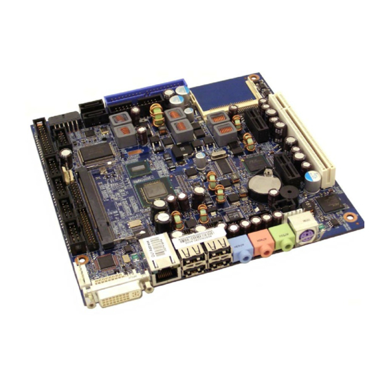
KTD-00774-D KTUS15/mITX Page 21 of 82 Connector layout 4.1.1 KTUS15/mITX – Top side FRONTPNL SATA1 SATA0 COMPACT FLASH Boot ROM PATA PRINTER USB6/7 COM4 PCIe x1 Slot 2 FAN CPU COM2 PCI Slot COM3 DDR2 SLOT COM1 PCIe x1 Slot 1... -
Page 22: Ktus15/Mitx - Io Bracket Side
KTD-00774-D KTUS15/mITX Page 22 of 82 4.1.2 KTUS15/mITX - IO Bracket side USB2 KBD/MSE DVI-A USB4 USB0 MIC-IN USB5 LINE-IN LINE-OUT 4.1.3 KTUS15/mITX – Back side SDIO2 SDIO1 Note: All connector except ”DDR2 SLOT”, “SDIO1” and “SDIO2” will be described in more details later in this chapter. -
Page 23: Power Connector (Pwr)
KTD-00774-D KTUS15/mITX Page 23 of 82 Power Connector (PWR) The KTUS15 boards shall be supplied by a single supply DC voltage in the range 5-25V DC +/-5%. Note Type Signal Signal Type Note +Vin +Vin +Vin +Vin +Vin +Vin The board will power on when the VIN voltage raises above 4.75V DC. -
Page 24: Power Out Connector (Pwr-Out)
KTD-00774-D KTUS15/mITX Page 24 of 82 Power Out Connector (PWR-OUT) External devices like HDD, CDROM etc. can be power sourced via the PWR-OUT connector. Signal Type Ioh/Iol Pull U/D Note 4A max +12V PWR 2A max Note: The PN 1027-3669 “Cable Power Out KTUS15” fits the PWR-OUT connector, and it has commonly used plugs in order to source power to different types of devices like PATA HDD, SATA devices, CDROM etc. -
Page 25: Keyboard And Mouse Connectors
KTD-00774-D KTUS15/mITX Page 25 of 82 Keyboard and Mouse connectors Attachment of a keyboard or PS/2 mouse adapter can be done through the MINI-DIN (KBD) connector or via the pinrow (KBDMSE) connector. All interfaces utilize open-drain signaling with on-board pull-up. -
Page 26: Display Connector
• LVDS Single channel 18/ 24bit interface Depending on the KTUS15/mITX board configuration (refer to section KTUS15/mITX Board configurations), the board is either configured for analogue (DVI-A) or digital display (DVI-D) output on the onboard DVI connector which is of the type DVI-I. In other words, even though onboard DVI connector is a type DVI-I simultaneous analogue and digital output is not possible on the DVI-I connector and it is not possible to change configuration from Analogue to Digital output or vice versa. -
Page 27: Dvi Connector (Dvi-D), Digital Output
KTD-00774-D KTUS15/mITX Page 27 of 82 4.5.2 DVI Connector (DVI-D), Digital output The DVI-D connector only support DVI Digital output. Female socket, front view Signal Description - DVI Connector: Signal Description Type Pull Up TMDS Data 2- Digital Red – (Link 1) -
Page 28: Lvds Flat Panel Connector (Lvds)
KTD-00774-D KTUS15/mITX Page 28 of 82 4.5.3 LVDS Flat Panel Connector (LVDS) Note Type Signal Signal Type Note Max. 0.5A +12V +12V PWR Max. 0.5A Max. 0.5A +12V +12V PWR Max. 0.5A Max. 0.5A +12V PWR Max. 0.5A Max. 0.5A PWR Max. -
Page 29: Pci-Express Connectors
KTD-00774-D KTUS15/mITX Page 29 of 82 PCI-Express connectors The KT boards contains two 1-lane (x1) PCI Express ports intended for external PCI Express cards. The PCI Express port is compliant to the PCI Express Base Specification revision 1.1. The two 1-lane (x1) PCI Express ports are supplied through an onboard 5-Lane/5-port PCI express switch. -
Page 30: Serial Ata Hard Disk Interface
Serial ATA Hard Disk interface The KTUS15 boards includes an onboard SATA interface depending on the configuration (refer to section KTUS15/mITX Board configurations). The SATA Host controller supports 2-port SATA II interface with data transfer rates of up to 3.0Gb/s (300MB/s). -
Page 31: Parallel Ata Hard Disk Interface
KTD-00774-D KTUS15/mITX Page 31 of 82 Parallel ATA Hard Disk interface The PATA Host Controller supports three types of data transfers: • Programmed I/O (PIO): Processor is in control of the data transfer. • Multi-word DMA (ATA-5): DMA protocol that resembles the DMA on the ISA bus. Allows transfer rates of up to 66MB/s. -
Page 32: Ide Hard Disk Connector (Pata)
KTD-00774-D KTUS15/mITX Page 32 of 82 4.8.1 IDE Hard Disk Connector (PATA) This connector can be used for connection of two primary IDE drives. Pull Ioh/ Ioh/ Pull Note Type Signal PIN# Signal Type Note RESET_P# DA10 9 10 DA11... -
Page 33: Compact Flash Connector (Cf)
Page 33 of 82 4.8.2 Compact Flash Connector (CF) This connector is mounted on the topside of the KTUS15/mITX. The CF socket support DMA/UDMA modules up to UDMA2. Note: If the CF connector is used then only one PATA device is supported and only by use of 40-wire cable (not 80-wire cable). -
Page 34: Printer Port Connector (Printer)
KTD-00774-D KTUS15/mITX Page 34 of 82 Printer Port Connector (PRINTER) The signal definition in standard printer port mode is as follows: Pull Pull Note Ioh/Iol Type Signal PIN# Signal Type Ioh/Iol Note 2K2 (24)/24 OC(O) STB# AFD# OC(O) (24)/24 2K2... -
Page 35: Serial Ports
4.10 Serial Ports Two or four RS232 serial ports are available on the KTUS15 boards depending on the configuration (refer to section KTUS15/mITX Board configurations). The typical definition of the signals in the COM ports is as follows: Signal Description Transmitted Data, sends serial data to the communications link. -
Page 36: Ethernet Connectors
KTD-00774-D KTUS15/mITX Page 36 of 82 4.11 Ethernet Connectors The KTUS15 board support 1 channel of 10/100/1000Mb Ethernet using the Intel® 82574L PCI express LAN controller. In order to achieve the specified performance of the Ethernet port, Category 5 twistedpair cables must be used with 10/100MB and Category 5E, 6 or 6E with 1Gb LAN networks. -
Page 37: Usb Connectors (Usb)
KTD-00774-D KTUS15/mITX Page 37 of 82 4.12 USB Connectors (USB) The KTUS15 boards contain three Universal Host Controller Interface (UHCI) USB1.1 controllers and an Enhanced Host Controller Interface (EHCI) USB2.0 controller. A total of eight USB ports are supported. All eight of these ports are capable of high speed data transfers up to 480MB/s, and six of the ports are also capable of FullSpeed and low-speed signaling (USB Ports 0, 1, 2, 3, 4, 5). -
Page 38: Usb Connector 0/2 (Usb0/2)
KTD-00774-D KTUS15/mITX Page 38 of 82 4.12.1 USB Connector 0/2 (USB0/2) Pull Pull Note Ioh/Iol Type Signal PIN# Signal Type Ioh/Iol Note USB5V /15K 0.25/2 USB0- USB0+ 0.25/2 /15K USB5V /15K 0.25/2 USB2- USB2+ 0.25/2 /15K Note 1: The 5V supply for the USB devices is fused onboard with a 2.0A resettable fuse. The supply is common to both channels. -
Page 39: Usb Connector 6/7 (Usb6/7)
KTD-00774-D KTUS15/mITX Page 39 of 82 4.12.3 USB Connector 6/7 (USB6/7) USB Ports 6 and 7 are supplied on the internal USB6, USB7 pinrow connector. USB6/7 are controlled only by the EHCI USB 2.0 controller and therefore they can only run USB2.0 HiSpeed (480Mbps). -
Page 40: Audio Connectors
KTD-00774-D KTUS15/mITX Page 40 of 82 4.13 Audio Connectors The onboard Audio circuit implements 7.1+2 Channel High Definition Audio, featuring ten 24-bit stereo DACs and two 20-bit stereo ADCs. The Audio signals are made available on the Frontpanel connectors (Line in / Line out / MIC) and the onboard AUDIO_HEAD and CDROM Audio input connectors. -
Page 41: Audio Header (Audio_Head)
KTD-00774-D KTUS15/mITX Page 41 of 82 4.13.3 Audio Header (AUDIO_HEAD) Pull Ioh/ Ioh/ Pull Note Type Signal PIN# Signal Type Note LFE-OUT CEN-OUT AAGND AAGND FRONT-OUT-L FRONT-OUT-R AAGND AAGND REAR-OUT-L 9 10 REAR-OUT-R SIDE-OUT-L 11 12 SIDE-OUT-R AAGND 13 14... -
Page 42: Fan Connector (Fan_Cpu)
KTD-00774-D KTUS15/mITX Page 42 of 82 4.14 Fan Connector (FAN_CPU) The FAN_CPU is used for the connection of the FAN for the CPU or the System. The 4pin header supports connection of 3-pin FAN, but it is recommended to use the 4-pin type for optimized FAN speed control. -
Page 43: Boot Rom Selection Jumper (Boot Rom)
KTD-00774-D KTUS15/mITX Page 43 of 82 4.15 Boot ROM Selection Jumper (BOOT ROM) The Boot ROM Selection Jumper shall only be moved from the Normal position (Boot onboard BIOS) in case the BIOS is corrupted and has to be recovered by use of the KT-BIOS-Recovery-Module. -
Page 44: Tpm Connector (Tpm)
KTD-00774-D KTUS15/mITX Page 44 of 82 4.17 TPM Connector (TPM) Pull Pull Note Ioh/Iol Type Signal Signal Type Ioh/Iol Note LPC CLK PWR LPC FRAME# LPC RST# LPC AD3 LPC AD2 +3V3 9 10 LPC AD1 LPC AD0 11 12... -
Page 45: Front Panel Connector (Frontpnl)
KTD-00774-D KTUS15/mITX Page 45 of 82 4.18 Front Panel Connector (FRONTPNL) Pull Ioh/ Ioh/ Pull Note Type Signal PIN# Signal Type Note USB10/11_5V USB10/11_5V USB1- USB3- USB1+ USB3+ 9 10 LINE2-IN-L 11 12 HD_LED 13 14 SUS_LED 15 16 PWRBTN_IN#... -
Page 46: Feature Connector (Feature)
KTD-00774-D KTUS15/mITX Page 46 of 82 4.19 Feature Connector (FEATURE) Pull Ioh/ Ioh/ Pull Note Type Signal PIN# Signal Type Note INTRUDER# EXT_ISAIRQ# PSUP_OFF 100K POWER_UP SB5V SB3V3 EXT_BAT 9 10 4K7/ /12mA IOT GPIO0 11 12 GPIO1 IOT /12mA 4K7/... -
Page 47: Pci Slot Connector (Pci Slot)
KTD-00774-D KTUS15/mITX Page 47 of 82 4.20 PCI Slot Connector (PCI Slot) Terminal Note Type Signal Signal Type Note -12V TRST# +12V INTA# INTB# INTC# INTD# REQ2# CLKC REQ3# +5V (I/O) PWR GNT2# CLKD CLKA GNT3# RST# CLKB +5V (I/O) PWR... -
Page 48: Signal Description - Pci Slot Connector
KTD-00774-D KTUS15/mITX Page 48 of 82 4.20.1 Signal Description – PCI Slot Connector SYSTEM PINS Clock provides timing for all transactions on PCI and is an input to every PCI device. All other PCI signals, except RST#, INTA#, INTB#, INTC#, and INTD#, are sampled on the risingedge of CLK and all other timing parameters are defined with respect to this edge. -
Page 49: Ktus15 Pci Irq & Int Routing
KTD-00774-D KTUS15/mITX Page 49 of 82 ARBITRATION PINS (BUS MASTERS ONLY) Request indicates to the arbiter that this agent desires use of the bus. This is a point to point signal. Every REQ# master has its own REQ# which must be tri-stated while RST# is asserted. -
Page 50: Onboard Connectors And Mating Connectors
KTD-00774-D KTUS15/mITX Page 50 of 82 Onboard connectors and Mating connectors Onboard Connectors Mating Connectors Connector Manufacturer Type no. Manufacturer Type no. FAN_CPU Foxconn HF2704E-M1 1375820-4 (4-pole) 1470947-1 1375820-3 (3-pole) KBDMSE Molex 22-23-2061 Molex 22-01-2065 CDROM Foxconn HF1104E Molex 50-57-9404... -
Page 51: System Resources
KTD-00774-D KTUS15/mITX Page 51 of 82 System Resources Memory Map Address (hex) Size Description 00000000 0009FFFF 655360 System board 000A0000 000BFFFF 131072 PCI-bus 000A0000 000BFFFF 131072 Intel(R) Graphics Media Accelerator 500 000C0000 000CFFFF 65536 System board 000D0000 000DFFFF 65536 PCI-bus... -
Page 52: Pci Devices
KTD-00774-D KTUS15/mITX Page 52 of 82 PCI Devices Device Function Vendor Device Chip Device Function 8086 10D3 82574L Gigabit Network Connection 8086 8117 US15W Enhanced USB2 Controller 8086 811B US15W High Definition Audio Controller 8686 8100 US15W Host Bridge 8086... -
Page 53: Interrupt Usage
KTD-00774-D KTUS15/mITX Page 53 of 82 Interrupt Usage Notes IRQ0 IRQ1 IRQ2 IRQ3 IRQ4 IRQ5 IRQ6 X manual OS selection IRQ7 IRQ8 IRQ9 IRQ10 IRQ11 IRQ12 IRQ13 IRQ14 IRQ15 IRQ16 IRQ17 IRQ18 IRQ19 IRQ20 IRQ21 IRQ22 IRQ23 IRQ24 IRQ25 IRQ26... -
Page 54: Io Map
KTD-00774-D KTUS15/mITX Page 54 of 82 IO Map Address range (hex) Size Description 3320 PCI-bus 001f Motherboard resources Programmable interrupt controller Motherboard resources System timer Motherboard resources Standard Keyboard System Speaker Motherboard resources Standard Keyboard Motherboard resources Motherboard resources System CMOS/Real time clock... -
Page 55: Overview Of Bios Features
Overview of BIOS Features This section details specific BIOS features for the KTUS15 board. The KTUS15 board is based on the AMI BIOS core version 8.10 with Kontron BIOS extensions. System Management BIOS (SMBIOS/DMI) SMBIOS is a Desktop Management Interface (DMI) compliant method for managing computers in a managed network. -
Page 56: Bios Configuration/Setup
KTD-00774-D KTUS15/mITX Page 56 of 82 BIOS Configuration/Setup Introduction The BIOS Setup is used to view and configure BIOS settings for the KTUS15 board. The BIOS Setup is accessed by pressing the DEL key after the Power-On Self-Test (POST) memory test begins and before the operating system boot begins. -
Page 57: Advanced Menu
KTD-00774-D KTUS15/mITX Page 57 of 82 Advanced Menu BIOS SETUP UTILITY Main Advanced PCIPnP Boot Security Chipset Exit Configure CPU. Advanced Settings Warning: Setting wrong values in below sections may cause system to malfunction. ► CPU Configuration ► IDE Configuration ►... -
Page 58: Advanced Settings - Cpu Configuration
KTD-00774-D KTUS15/mITX Page 58 of 82 7.3.1 Advanced settings – CPU Configuration BIOS SETUP UTILITY Advanced Disabled for WindowsXP Configure advanced CPU settings Module Version: 3F.12 Manufacturer: Intel Intel® Atom™ CPU Z530 @ 1.60Ghz Frequency : 1.59Ghz FSB Speed : 533Mhz... -
Page 59: Advanced Settings - Ide Configuration
KTD-00774-D KTUS15/mITX Page 59 of 82 7.3.2 Advanced settings – IDE Configuration BIOS SETUP UTILITY Advanced Options IDE Configuration Disabled [Compatible] ATA/IDE Configuration Compatible ► Primary IDE Master [Hard Disk] ► Primary IDE Slave [Not Detected] ► Third IDE Master [Not Detected] ►... - Page 60 KTD-00774-D KTUS15/mITX Page 60 of 82 BIOS SETUP UTILITY Advanced Select the type of Primary IDE Master devices connected to the system Device :Hard Disk Vendor :ST340014A Size :40.0GB LBA Mode :Supported Block Mode :16Sectors PIO Mode Async DMA :MultiWord DMA-2...
-
Page 61: Advanced Settings - Lan Configuration
KTD-00774-D KTUS15/mITX Page 61 of 82 7.3.3 Advanced settings – LAN Configuration BIOS SETUP UTILITY Advanced Control of Ethernet LAN Configuration Devices and PXE boot ETH1 Configuration [Enabled] MAC Address & Link status : 00E0F41E24A4 1GB <-> Select Screen Select Item... -
Page 62: Advanced Settings - Configure Win627Dhg Super Io Chipset
KTD-00774-D KTUS15/mITX Page 62 of 82 7.3.4 Advanced settings – Configure Win627DHG Super IO Chipset BIOS SETUP UTILITY Advanced Allows BIOS to Enable Configure Win627DHG Super IO Chipset or Disable Floppy Controller. Serial Port1 Address [3F8/IRQ4] Serial Port2 Address [2F8/IRQ3]... - Page 63 KTD-00774-D KTUS15/mITX Page 63 of 82 Feature Options Description Serial Port3 Address Allows BIOS to select Serial Port3 Base Addresses Disabled (The available options depend on the setup for the other Serial Ports). Serial Port3 IRQ IRQ3 Allows BIOS to select Serial Port3 IRQ.
-
Page 64: Advanced Settings - Hardware Health Configuration
KTD-00774-D KTUS15/mITX Page 64 of 82 7.3.5 Advanced settings – Hardware Health Configuration BIOS SETUP UTILITY Advanced Disable = Full Speed Hardware Health Configuration Thermal: Does regulate System Temperature :48ºC/118ºF fan speed according to CPU Temperature :56ºC/132ºF specified temperature VTIN Temperature... -
Page 65: Advanced Settings - Voltage Monitor
KTD-00774-D KTUS15/mITX Page 65 of 82 7.3.6 Advanced settings – Voltage Monitor BIOS SETUP UTILITY Advanced Voltage Monitor Requested Core CPU :1.100 V Vcore :1.096 V AVCC :3.248 V 3VCC :3.248 V +12V :12.029 V :5.016 V Core 1.8 V :1.800 V... -
Page 66: Advanced Settings - Acpi Settings
KTD-00774-D KTUS15/mITX Page 66 of 82 7.3.7 Advanced settings – ACPI Settings BIOS SETUP UTILITY Advanced General ACPI ACPI Settings Configuration settings ► General ACPI Configuration ► Advanced ACPI Configuration PS/2 Kbd/Mouse S4/S5 Wake [Disabled] Keyboard Wake Hotkey [Any key]... -
Page 67: Advanced Settings - Pci Express Configuration
KTD-00774-D KTUS15/mITX Page 67 of 82 7.3.8 Advanced settings – PCI Express Configuration BIOS SETUP UTILITY Advanced Enable/Disable PCI Express Configuration PCI Express L0s and L1 link power States. Active State Power-Management [Enabled] <-> Select Screen Select Item change option... -
Page 68: Advanced Settings - Trusted Support
KTD-00774-D KTUS15/mITX Page 68 of 82 7.3.10 Advanced settings – Trusted Support BIOS SETUP UTILITY Advanced Enables/Disable TPM TCG Trusted Computing (Tpm 1.1/1.2) Support in Bios TCG/TPM Support [No] <-> Select Screen Select Item change option General Help Save and Exit Exit V02.63+ (C)Copyright 1985-2008, American Megatrends, Inc. -
Page 69: Advanced Settings - Usb Configuration
KTD-00774-D KTUS15/mITX Page 69 of 82 7.3.11 Advanced settings – USB Configuration BIOS SETUP UTILITY Advanced Enables support for USB Configuration legacy USB. AUTO option disables legacy support Module Version – 2.24.2-13.4 if no USB Devices are connected. USB Devices Enabled :... -
Page 70: Advanced Settings - Usb Mass Storage Device Configuration
KTD-00774-D KTUS15/mITX Page 70 of 82 7.3.12 Advanced settings – USB Mass Storage Device Configuration BIOS SETUP UTILITY Advanced Number of seconds POST USB Mass Storage Device Configuration waits for the USB mass storage device after USB Mass Storage Reset Delay [20 Sec] start unit command. -
Page 71: Pcipnp Menu
KTD-00774-D KTUS15/mITX Page 71 of 82 PCIPnP Menu BIOS SETUP UTILITY Main Advanced PCIPnP Boot Security Chipset Exit Clear NVRAM during Advanced PCI/PnP Settings System Boot. Warning: Setting wrong values in below sections May cause system to malfunction. Clear NVRAM [No] Plug &... -
Page 72: Boot Menu
KTD-00774-D KTUS15/mITX Page 72 of 82 Boot Menu BIOS SETUP UTILITY Main Advanced PCIPnP Boot Security Chipset Exit Configure Settings Boot Settings during System Boot. ► Boot Settings Configuration ► Boot Device Priority <-> Select Screen Select Item Enter Go to Sub Screen... -
Page 73: Boot - Boot Settings Configuration
KTD-00774-D KTUS15/mITX Page 73 of 82 7.5.1 Boot – Boot Settings Configuration BIOS SETUP UTILITY Boot Allows BIOS to skip Boot Settings Configuration certain tests while booting. This will Quick Boot [Enabled] decrease the time needed Quiet Boot [Disabled] to boot the system. -
Page 74: Boot - Boot Device Priority
KTD-00774-D KTUS15/mITX Page 74 of 82 7.5.2 Boot – Boot Device Priority BIOS SETUP UTILITY Boot Specifies the boot Boot Device Priority sequence from the available devices. 1st Boot Device [ESS-ST380811AS] A device enclosed in parenthesis has been disabled in the corresponding type menu. -
Page 75: Security Menu
KTD-00774-D KTUS15/mITX Page 75 of 82 Security Menu BIOS SETUP UTILITY Main Advanced PCIPnP Boot Security Chipset Exit Install or Change the Security Settings password. Supervisor Password :Not Installed User Password :Not Installed Change Supervisor Password Change User Password Boot Sector Virus Protection [Disabled] <->... - Page 76 KTD-00774-D KTUS15/mITX Page 76 of 82 Supervisor Password protection (setup Supervisor before User) Super- visor BIOS User Access control Full Date&Time * Supervisor PSW CMOS (most) View User Limit None * = also: Quick Boot Quiet Boot Repost Video on S3 Resume...
-
Page 77: Chipset Menu
KTD-00774-D KTUS15/mITX Page 77 of 82 Chipset Menu BIOS SETUP UTILITY Main Advanced PCIPnP Boot Security Chipset Exit Configures North Bridge Advanced Chipset Settings features. Warning: Setting wrong values in below sections may cause system to malfunction. ► North Bridge Configuration ►... -
Page 78: Advanced Chipset
KTD-00774-D KTUS15/mITX Page 78 of 82 7.7.2 Advanced Chipset … – North Bridge … – Boot Display Configuration BIOS SETUP UTILITY Chipset Options Boot Display Configuration Auto Boot Display Device [Auto] Integrated LVDS Local Flat Panel Scaling [Auto] External DVI/HDMI... -
Page 79: Advanced Chipset Settings - South Bridge Chipset Configuration
KTD-00774-D KTUS15/mITX Page 79 of 82 7.7.3 Advanced Chipset Settings – South Bridge Chipset Configuration BIOS SETUP UTILITY Chipset Number of UCHI South Bridge Chipset Configuration Ports in system ECHI ONLY is automatically USB Functions [6 USB Ports] Added. USB 2.0 Controller... -
Page 80: Exit Menu
KTD-00774-D KTUS15/mITX Page 80 of 82 Exit Menu BIOS SETUP UTILITY Main Advanced PCIPnP Boot Security Chipset Exit Exit system setup after Exit Options saving the changes. Save Changes and Exit F10 Key can be used for Discard Changes and Exit this operation. -
Page 81: Ami Bios Beep Codes
KTD-00774-D KTUS15/mITX Page 81 of 82 AMI BIOS Beep Codes Boot Block Beep Codes: Number of Description Beeps Insert diskette in floppy drive A: ‘AMIBOOT.ROM’ file not found in root directory of diskette in A: Base Memory error Flash Programming successful... -
Page 82: Os Setup
Refer to configuration overview: KTUS15/mITX Board configurations for details. Warranty KONTRON Technology warrants its products to be free from defects in material and workmanship during the warranty period. If a product proves to be defective in material or workmanship during the warranty period, KONTRON Technology will, at its sole option, repair or replace the product with a similar product.
Need help?
Do you have a question about the KTUS15/mITX and is the answer not in the manual?
Questions and answers