Table of Contents
Advertisement
Quick Links
Advertisement
Table of Contents

Subscribe to Our Youtube Channel
Related Manuals for Kontron KTG41/ATXu


Summary of Contents for Kontron KTG41/ATXu
- Page 1 KTG41/ATXu KTG41 Users Guide KTD-00781-A If it’s embedded, it’s Kontron.
-
Page 2: Document Revision History
Brand and product names are trademarks or registered trademarks of their respective owners. Disclaimer: KONTRON Technology A/S reserves the right to make changes, without notice, to any product, including circuits and/or software described or contained in this manual in order to improve design and/or performance. -
Page 3: Life Support Policy
KONTRON Technology Technical Support and Services If you have questions about installing or using your KONTRON Technology Product, check this User’s Manual first – you will find answers to most questions here. To obtain support, please contact your local Distributor or Field Application Engineer (FAE). -
Page 4: Table Of Contents
PCI-Express x16/SDVO Connector (PCIe x16/SDVO) ............. 26 3.5.2 PCI-Express x4 Connector (PCIe x4)..................28 IDE Hard Disk Connector (PATA)....................30 Serial ATA Hard Disk interface ....................31 3.7.1 SATA Hard Disk Connector (SATA1, SATA2, SATA3, SATA4)..........31 Printer Port Connector (LPT) ...................... 32 www.kontron.com... - Page 5 System Resources................50 Memory Map ..........................50 PCI Devices ..........................51 Interrupt Usage ........................... 52 IO Map ............................53 Overview of BIOS Features ............54 System Management BIOS (SMBIOS/DMI) ................54 Legacy USB Support ........................54 BIOS Update ..........................54 www.kontron.com...
- Page 6 Advanced Chipset … – North Bridge … – Video Function Configuration ......... 74 6.9.3 Advanced Chipset … – South Bridge Chipset Configuration ............ 75 6.10 Exit Menu ............................ 76 AMI BIOS Beep Codes ..............77 OS Setup ..................78 Warranty ..................78 www.kontron.com...
-
Page 7: Introduction
KTG41 family Page 7 of 78 Introduction This manual describes the KTG41/ATXu board made by KONTRON Technology A/S. The board will also be denoted KTG41. The KTQ41 boards supports the Intel® Core™2 Quad processor Q9000 series, the Intel® Core™2 Duo processor E7000 and E8000 series with a maximum TDP of 95W. -
Page 8: Installation Procedure
Installation procedure Installing the board To get the board running, follow these steps. In some cases the board shipped from KONTRON Technology has DDR3 DRAM mounted. In this case Step 2 can be skipped. 1. Turn off the power supply Warning: Do not use Power Supply without 3.3V monitoring watchdog, which is standard... - Page 9 When fixing the Motherboard on a chassis it is recommended using screws with integrated washer and having diameter of ~7mm. Note: Do not use washers with teeth, as they can damage the PCB mounting hole and may cause short circuits. www.kontron.com...
-
Page 10: Requirement According To En60950
Paristo voi räjähtää, jos se on virheellisesti Explosionsfara vid felaktigt batteribyte. asennettu. Använd samma batterityp eller en ekvivalent Vaihda paristo ainoastaan laltevalmistajan typ som rekommenderas av apparattillverkaren. suosittelemaan Kassera använt batteri enligt fabrikantens tyyppiln. Hävitä käytetty paristo valmistajan instruktion. ohjeiden mukaisesti. www.kontron.com... -
Page 11: System Specification
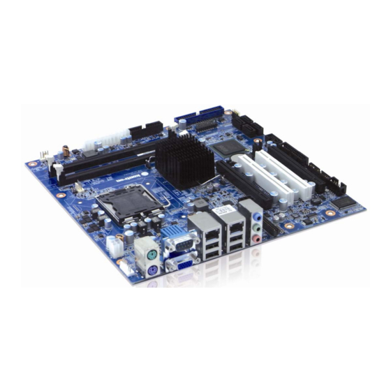
KTG41 family Page 11 of 78 System specification Component main data The table below summarizes the features of the KTG41/ATXu embedded motherboard. KTG41/ATXu: Micro-ATX (243,84millimeters by 243,84millimeters) Form factor • Support for Supports Intel® Core™2 Quad processor Q9000 series, Supports Intel®... - Page 12 Current draw is 5-6µA when PSU is disconnected. CAUTION: Danger of explosion if the battery is incorrectly replaced. Replace only with the same or equivalent type recommended by the manufacturer. Dispose of used batteries according to the manufacturer’s instructions. www.kontron.com...
-
Page 13: System Overview
KTG41 family Page 13 of 78 System overview The block diagram below shows the architecture and main components of the KTG41 board. The two key ® ® components on the board are the Intel G41 and Intel ICH7R Chipsets. www.kontron.com... -
Page 14: Processor Support Table
Intel® Core™ 2 Quad Processor Intel® Core™ 2 Duo Processor Intel® Pentium® Processor (2 cores) Intel® Celeron® In the following list the CPU Number in emphases means supported in according to Intel, but pt. not tested by Kontron. Clock sSpec Thermal Cache... - Page 15 2.70 (E5400) Intel® Pentium® (2 Cores) 2.60 (E5300) (Conroe) 2.50 (E5200) 2.40 (E2220) 2.20 (E2200) 2.00 (E2180) 1.80 E2160 SLA8Z 1.60 (E2140) 2.40 (E1600) Intel® Celeron® 2.20 (E1500) (Conroe) 2.00 (E1400) 1.60 (E1200) 2.00 (440) 1.80 (430) 1.60 (420) www.kontron.com...
-
Page 16: System Memory Support
1333 1066 PC3-8500 8533 Note: Kontron offers the following memory modules: • P/N 1028-6891, DDR3-RAM, 1GB, 240p, 800MHZ, PC3-8500, DIMM • P/N 1028-6892, DDR3-RAM, 2GB, 240p, 800MHZ, PC3-8500, DIMM Memory Configurations 1. Asymmetric mode (Single channel). This mode is equivalent to single channel bandwidth operation. This mode is used when only one DIMM is installed or two DIMMs with different memory capacities are installed. -
Page 17: Ktg41 Graphics Subsystem
An example of this would be when using VGA graphics under DOS. Once loaded, the operating system and graphics drivers allocate additional system memory to the graphics buffer as needed for performing graphics functions. IMPORTANT: The use of DVMT requires driver support by the operating system. www.kontron.com... -
Page 18: Add2 (Advanced Digital Display) Card Support
• VGA output • HDTV output • HDMI/UDI support (when used with the HD Audio Link) Currently Kontron plans the availability of the following ADD2 cards • P/N 820953, ADD2-LVDS • P/N 820950, ADD2-Dual LVDS • P/N 820951, ADD2-Dual Internal DVI •... -
Page 19: Power Consumption
Test system configuration Test system configuration The following items were used in the test setup: 1. KTG41/ATXu board mounted w/ 3.00GHz (E8400) Core Duo & 1GB Samsung 1Rx8 PC3-10600U-09- 00-A0 1,5V DDR3 Ram 2. 12V active cooler 3. PS/2 keyboard & mouse (Mouse:Genius Netscroll+ Keyboard:ACK-595) 4. - Page 20 Current draw Power consumption 0.00A +12V 0.00A 0.00A +3V3 0.00A -12V 0.49A 2.45W 5VSB 2.45W Total S4 Mode, Mean, No external load Supply Current draw Power consumption 0.00A +12V 0.00A 0.00A +3V3 0.00A -12V 0.44A 2.20W 5VSB 2.20W Total www.kontron.com...
-
Page 21: Connector Definitions
On-board pull-up or pull-down resistors on input pins or open-collector output pins. Note Special remarks concerning the signal. The abbreviation TBD is used for specifications which are not available yet or which are not sufficiently specified by the component vendors. www.kontron.com... -
Page 22: Connector Layout
COM2 KBDMSE ATX+12V-6pin CDROM AUDIO_HEAD * JP5 / JP4 used for BIOS boot selection (only for manufacture purpose) JBAT1 used for Clear CMOS 3.1.2 KTG41 - IO Bracket area ETHER1 USB5 COM1 USB4 ETHER2 AUDIO USB7 STACK (PS2) USB6 www.kontron.com... -
Page 23: Power Connector (Atx/Btxpwr)
5V and 3V3 supplies. These supplies are not supervised onboard the KTG41. PS_ON# Active low open drain signal from the board to the power supply to turn on the power supply outputs. Signal must be pulled high by the power supply. www.kontron.com... -
Page 24: Keyboard And Mouse Connectors
Bi-directional serial data line used to transfer data from or commands to the PS/2 mouse. KDBCLK Bi-directional clock signal used to strobe data/commands from/to the PC-AT keyboard. KBDDAT Bi-directional serial data line used to transfer data from or commands to the PC-AT keyboard. www.kontron.com... -
Page 25: Display Connector
No Connection DDCDAT Display Data Channel Data. Used as data signal to/from monitors with DDC interface. HSYNC CRT horizontal synchronization output. VSYNC CRT vertical synchronization output. DDCCLK Display Data Channel Clock. Used as clock signal to/from monitors with DDC interface. www.kontron.com... -
Page 26: Pci-Express Connectors
SMB_CLK SMB_DATA +3V3 +3V3 SB3V3 +3V3 WAKE# RST# PCIE_x16 CLK PEG_TXP[15]/SDVOB_RED PCIE_x16 CLK# PEG_TXN[15]/SDVOB_RED# PEG_RXP[15]/SDVO_TVCLKIN SDVO_CTRLCLK PEG_RXN[15] / SDVO_TVCLKIN# PEG_TXP[14]/SDVOB_GREEN PEG_TXN[14]/SDVOB_GREEN# PEG_RXP[14]/SDVOB_INT PEG_RXN[14]/SDVOB_INT# PEG_TXP[13]/SDVOB_BLUE PEG_TXN[13]/SDVOB_BLUE# PEG_RXP[13]/SDVO_FLDSTALL PEG_RXN[13]/SDVO_FLDSTALL# PEG_TXP[12]/SDVOB_CLKP PEG_TXN[12]/SDVOB_CLKN PEG_RXP[12] PEG_RXN[12] SDVO_CTRLDATA PEG_TXP[11]/SDVOC_RED PEG_TXN[11]/SDVOC_RED# PEG_RXP[11] PEG_RXN[11] PEG_TXP[10]/SDVOC_GREEN PEG_TXN[10]/SDVOC_GREEN# PEG_RXP[10]/SDVOC_INT www.kontron.com... - Page 27 PEG_RXP[9] PEG_RXN[9] PEG_TXP[8]/SDVOC_CLKN PEG_TXN[8]/SDVOC_CLKP PEG_RXP[8] PRSNT#2 PEG_RXN[8] PEG_TXP[7] PEG_TXN[7] PEG_RXP[7] PEG_RXN[7] PEG_TXP[6] PEG_TXN[6] PEG_RXP[6] PEG_RXN[6] PEG_TXP[5] PEG_TXN[5] PEG_RXP[5] PEG_RXN[5] PEG_TXP[4] PEG_TXN[4] PEG_RXP[4] PEG_RXN[4] PEG_TXP[3] PEG_TXN[3] PEG_RXP[3] PEG_RXN[3] PEG_TXP[2] PEG_TXN[2] PEG_RXP[2] PEG_RXN[2] PEG_TXP[1] PEG_TXN[1] PEG_RXP[1] PEG_RXN[1] PEG_TXP[0] PEG_TXN[0] PEG_RXP[0] PEG_RXN[0] www.kontron.com...
-
Page 28: Pci-Express X4 Connector (Pcie X4)
Note Type Signal Signal Type Note +12V +12V +12V +12V +12V SMB_CLK SMB_DATA +3V3 +3V3 SB3V3 +3V3 WAKE# RST# PCIE_x4 CLK PCIE_TXP[1] PCIE_x4 CLK# PCIE_TXN[1] PCIE_RXP[1] PCIE_RXN[1] PCIE_TXP[2] PCIE_TXN[2] PCIE_RXP[2] PCIE_RXN[2] PCIE_TXP[3] PCIE_TXN[3] PCIE_RXP[3] PCIE_RXN[3] PCIE_TXP[4] PCIE_TXN[4] PCIE_RXP[4] PCIE_RXN[4] www.kontron.com... - Page 29 KTD-00781-A KTG41 family Page 29 of 78 www.kontron.com...
-
Page 30: Ide Hard Disk Connector (Pata)
HDACTA# Signal from hard disk indicating hard disk activity. The signal level depends on the hard disk type, normally active low. The signals from primary and secondary controller are routed together through diodes and passed to the connector FEATURE. www.kontron.com... -
Page 31: Serial Ata Hard Disk Interface
The signals used for the primary Serial ATA hard disk interface are the following: Signal Description SATA* RX+ Host transmitter differential signal pair SATA* RX- Host receiver differential signal pair SATA* TX+ SATA* TX- “*” specifies 1, 2, 3, 4 depending on SATA port. www.kontron.com... -
Page 32: Printer Port Connector (Lpt)
This active low output causes the printer to add a line feed after each line printed. ERR# Signal from printer indicating that an error has been detected. Signal from printer indicating that the printer is out of paper. The printer port additionally supports operation in the EPP and ECP mode. www.kontron.com... -
Page 33: Serial Ports
The connector pinout for each operation mode is defined in the following sections. 3.9.1 COM1 Connectors COM1 is RS232 port available in the IO Bracket area. The pinout of Serial ports Com1 is as follows: Pull Pull Note Ioh/Iol Type Signal PIN Signal Type Ioh/Iol Note www.kontron.com... -
Page 34: Com2 Header Connectors
9 10 Note 1: The COM2 5V supply is fused with 1.1A resettable fuse. Ribbon cable kits (Kontron PN 821016 or PN 821017) are available for converting the COM2 pin header connector to a DB9 connector for I/O panel. www.kontron.com... -
Page 35: Ethernet Connectors
Ethernet connector 1 is mounted together with USB Ports 4 and 5. Ethernet connector 2 is mounted together with USB Ports 6 and 7. The pinout of the RJ45 connectors is as follows: Signal Type Ioh/Iol Note MDI0+ MDI0- MDI1+ MDI2+ MDI2- MDI1- MDI3+ MDI3- www.kontron.com... -
Page 36: Usb Connectors (Usb)
Signal Description Differential pair works as Data/Address/Command Bus. USB4+ USB4- USB5+ USB5- 5V/SB5V 5V supply for external devices. SB5V is supplied during powerdown to allow wakeup on USB device activity. Protected by resettable 1.1A fuse covering both USB ports. www.kontron.com... -
Page 37: Usb Connector 6/7 (Usb6/7)
USB1+ USB1- 5V/SB5V 5V supply for external devices. SB5V is supplied during powerdown to allow wakeup on USB device activity. Protected by resettable 1.1A fuse covering both USB ports. 3.11.4 USB Connector 2/3 (USB2/3) See Frontpanel Connector (FRONTPNL) description. www.kontron.com... -
Page 38: Audio Connectors
Front speaker out Front speaker out Front speaker out Lime Mic in Mic in Mic in Mic in Pink Side speaker out Audio header Rear speaker out Rear speaker out Rear speaker out Audio header Center/ Subwoofer Center/ Subwoofer Audio header www.kontron.com... -
Page 39: Cdrom Audio Input (Cdrom)
Some CDROM cable kits expect reverse pin order. Signal Description CD_Left Left and right CD audio input lines or secondary Line-in. CD_Right CD_GND Analogue GND for Left and Right CD. (This analogue GND is not shorted to the general digital GND on the board). www.kontron.com... -
Page 40: Audio Header (Audio_Head)
Side speakers (Surround Out Right) CEN-OUT Center Speaker (Center Out channel). LFE-OUT Subwoofer Speaker (Low Freq. Effect Out). No connection MIC1 MIC Input 1 LINE1-IN Line in 1 signals F-SPDIF-IN S/PDIF Input F-SPDIF-OUT S/PDIF Output AAGND Audio Analogue ground www.kontron.com... -
Page 41: Fan Connector (Fan_Cpu)
Onboard is a pull-up resistor 4K7 to +12V. The signal has to be pulsed, typically twice per rotation. +12V supply for fan, can be turned on/off or modulated (PWM) by the chipset. A maximum of 2000mA can be supplied from this pin. Power Supply GND signal www.kontron.com... -
Page 42: Clear Cmos Jumper (Clr-Cmos /Jbat1)
The SPI selection jumper is used to switch between onboard SPI and external SPI device. Note: The SPI device holds the BIOS contents and should not be removed from its default position unless a pre-programmed SPI device is connected to the SPI1 connector. • Pin 2-3 is default position (SPI connectors) www.kontron.com... -
Page 43: Tpm Connector (Tpm)
SMB_DATA SB3V3 15 16 LPC SERIRQ 17 18 CLKRUN# SUS_STAT# 19 20 3.17 SPI Connector (SPI) Pull Pull Note Ioh/Iol Type Signal Signal Type Ioh/Iol Note SPI_CLK SB3V3 PWR BOOT0 10K/ SPI_CS2# BOOT1 10K/ SPI_MOSI 10K/ SPI_MISO 9 10 www.kontron.com... -
Page 44: Front Panel Connector (Frontpnl)
Line in 2 signals MIC2 MIC2-L and MIC2-R is second stereo microphone input. SB3V3 Standby 3.3V voltage AGND Analogue Ground for Audio Note 1: In order to meet the requirements of USB standard, the 5V input supply must be at least 5.00V. www.kontron.com... -
Page 45: Feature Connector (Feature)
Voltage REFerence, reference voltage to be used with TEMP3IN input. IRRX IR Receive input (IrDA 1.0, SIR up to 1.152K bps) IRTX IR Transmit output (IrDA 1.0, SIR up to 1.152K bps) SMBC SMBus Clock signal SMBD SMBus Data signal www.kontron.com... -
Page 46: Pci Slot Connector (Pci Slot)
PERR# SDONE +3.3V SB0# SERR# +3.3V C/BE1# AD15 AD14 +3.3V AD13 AD12 AD11 AD10 AD09 SOLDER SIDE COMPONENT SIDE AD08 C/BE0# AD07 +3.3V +3.3V AD06 AD05 AD04 AD03 AD02 AD01 AD00 PWR +5V (I/O) +5V (I/O) PWR ACK64# REQ64# www.kontron.com... -
Page 47: Signal Description - Pci Slot Connector
Initialization Device Select is used as a chip select during configuration read and write transactions. IDSEL Device Select, when actively driven, indicates the driving device has decoded its address as the target of DEVSEL# the current access. As an input, DEVSEL# indicates whether any device on the bus has been selected. (Continues) www.kontron.com... -
Page 48: Ktg41 Pci Irq & Int Routing
INTC INTD AD16 INT_PIRQ#A INT_PIRQ#B INT_PIRQ#C INT_PIRQ#D KTG41/ATXu AD17 INT_PIRQ#E INT_PIRQ#F INT_PIRQ#G INT_PIRQ#H When using the 820982 “PCI Riser - Flex - 2slot w. arbiter” the lower slot has IDSEL / IRQs routed straight through and the top slot has the routing: IDSEL=AD22, INT_PIRQ#F, INT_PIRQ#G, INT_PIRQ#H, INT_PIRQ#E. -
Page 49: Onboard Connectors And Mating Connectors
22-23-2061 Molex 22-01-2065 CDROM Foxconn HF1104E Molex 50-57-9404 Molex 70543-0038 SATA1-4 Hon Hai LD1807V-S52T Molex 67489-8005 Kontron KT 821035 (cable kit) ATXPWR Molex 43045-1201 Molex 43025-1200 KT 1022-6309 (cable kit Kontron for ATX PSU) ATX+12V-4pin Molex 22-23-2041 Molex 22-01-2046 Kontron... -
Page 50: System Resources
FED1C000 FED1FFFF 16384 Motherboard resources FED20000 FED3FFFF 131072 Motherboard resources FED90000 FED93FFF 16384 System board FEE00000 FEE00FFF 4096 Motherboard resources FFB00000 FFBFFFFF 1048576 Intel(R) 82802 Firmware Hub FFC00000 FFEFFFFF 3145728 Motherboard resources FFF00000 FFFFFFFF 1048576 Intel(R) 82802 Firmware Hub www.kontron.com... -
Page 51: Pci Devices
PCI to PCI bridge 8086 27B8 Intel ICH7 ISA bridge 8086 27DF Intel ICH7 IDE Controller 8086 27C0 Intel ICH7 IDE Controller 8086 27DA Intel ICH7 SMBus 11AB 436B Marvell 88E8071 Ethernet Controller 11AB 436B Marvell 88E8071 Ethernet Controller www.kontron.com... -
Page 52: Interrupt Usage
KTD-00781-A KTG41 family Page 52 of 78 Interrupt Usage IRQ0 IRQ1 IRQ2 IRQ3 IRQ4 IRQ5 IRQ6 IRQ7 IRQ8 IRQ9 IRQ10 IRQ11 IRQ12 IRQ13 IRQ14 IRQ15 IRQ16 IRQ17 IRQ18 IRQ19 IRQ20 IRQ21 IRQ22 IRQ23 IRQ24 IRQ25 IRQ26 www.kontron.com... -
Page 53: Io Map
Marvell Yukon 88E8071 PCI-E Gigabit Ethernet Controller E000 EFFF 4096 Intel(R) 82801GR/GH/GHM (ICH7 Family) PCI Express Root Port - 27E0 E800 E8FF Marvell Yukon 88E8071 PCI-E Gigabit Ethernet Controller #2 FFA0 FFAF Intel(R) 82801G (ICH7 Family) Ultra ATA Storage Controllers - 27DF www.kontron.com... -
Page 54: Overview Of Bios Features
Enabled and follow the operating system’s installation instructions. BIOS Update The BIOS can be updated using Kontron utility called bf.exe, which are included in BIOS packages available on the Kontron Web site. The utility supports DOS and Windows environment. -
Page 55: Bios Configuration/Setup
System Date [Thu 14/09/2009] v02.61 (C)Copyright 1985-2006, American Megatrends, Inc. You can make the following selections. Use the sub menus for other selections. Feature Options Description System Time HH:MM:SS Set the system time. System Date MM/DD/YYYY Set the system date. www.kontron.com... -
Page 56: Advanced Menu
► SuperIO Configuration ► Hardware Health Configuration ► Voltage Monitor ► ACPI Configuration ► Trusted Computing ► USB Configuration <- Select Screen Select Item Enter Go to Sub Screen General Help Save and Exit Exit v02.61 (C)Copyright 1985-2006, American Megatrends, Inc. www.kontron.com... -
Page 57: Advanced Settings - Cpu Configuration
A full reset is required to change the setting. Execute-Disable Bit Capability Disabled When disabled, force the XD feature flag to always return 0. Enabled Core Multi-Processing Disabled When disabled, disable one execution core of each CPU die. Enabled PECI Disabled When enabled, enables PECI interface. Enabled www.kontron.com... -
Page 58: Advanced Settings - Ide Configuration
Hard Disk Write Protect Disable/Enable device write protection. This will be Disabled Enabled effective only if device is accessed through BIOS IDE Detect Time Out (Sec) Select the timeout value for detecting ATA/ATAPI device(s) Sata BIOS Extension Disabled Disabled Enabled Enabled www.kontron.com... - Page 59 UDMA2 UDMA3 UDMA4 UDMA5 UDMA6 S.M.A.R.T. Select if the Device should be monitoring itself (Self- Auto Disabled Monitoring, Analysis and Reporting Technology Enabled System) 32Bit Data Transfer Disabled* Select if the Device should be using 32Bit data Transfer Enabled www.kontron.com...
-
Page 60: Advanced Settings - Lan Configuration
With RPL/PXE boot Feature Options Description ETH2 Configuration Disabled Disable/enable LAN or enabled with RPL/PXE boot Enabled With RPL/PXE boot Note: The “+” and “-“ (to the right of the MAC address) indicates if link is established or not. www.kontron.com... -
Page 61: Advanced Settings - Configure Win627Dhg Super Io Chipset
Select a DMA channel in ECP mode of operation ECP Mode DMA Channel DMA1 DMA3 If EPP mode: Select version of EPP in the EPP mode of operation EPP Version Parallel Port IRQ IRQ5 Select a IRQ for the Parallel Port IRQ7 www.kontron.com... -
Page 62: Advanced Settings - Hardware Health Configuration
4 Wire = 12VDC always PWM on control signal Watchdog To be serviced via API. Disabled 15 seconds 30 seconds 1 minute 2 minutes 5 minutes 10 minutes Note: The AUXFAN is available via Feature Connector. www.kontron.com... -
Page 63: Advanced Settings - Voltage Monitor
:3.232 V P12V :11.827 V -12Vin :Good <-> Select Screen :5.077 V Select Item DDR1V5 :1.512 V change option P1V5 :1.480 V General Help :3.216 V Save and Exit VBAT :3.088 V Exit v02.61 (C)Copyright 1985-2006, American Megatrends, Inc. www.kontron.com... -
Page 64: Advanced Settings - Acpi Settings
[Auto] <-> Select Screen Select Item change option General Help Save and Exit Exit v02.61 (C)Copyright 1985-2006, American Megatrends, Inc. Feature Options Description Suspend mode S1 (POS) * Select the ACPI state used for System Suspend. S3 (STR) Auto www.kontron.com... -
Page 65: Advanced Settings - Trusted Support
TPM Enable/Disable Status [No State] TPM Owner Status [No State] <-> Select Screen Select Item change option General Help Save and Exit Exit v02.61 (C)Copyright 1985-2006, American Megatrends, Inc. Feature Options Description TCG/TPM Support Enables/Disable TPM TCG (TPM 1.1/1.2) Support. www.kontron.com... -
Page 66: Advanced Settings - Usb Configuration
Note: This feature is not available when Failsafe Defaults are loaded, because USB2.0 controller is disabled as default. Bios EHCI Hand-off Disabled This is a workaround for OSes without EHCI hand-off support. The EHCI ownership change Enabled should claim by EHCI driver. www.kontron.com... -
Page 67: Advanced Settings - Usb Mass Storage Device Configuration
If Auto, USB devices less than 530MB will be Auto Floppy emulated as Floppy and remaining as hard Forced FDD drive. Forced FDD option can be used to force Hard Disk a HDD formatted drive to boot as FDD (Ex. CDROM ZIP drive). www.kontron.com... -
Page 68: Boot Menu
[USB Flash Memory] <-> Select Screen Select Item Enter Go to Sub Screen General Help Save and Exit Exit v02.61 (C)Copyright 1985-2006, American Megatrends, Inc. Note: When pressing <F11> while booting it is possible manually to select boot device. www.kontron.com... -
Page 69: Boot - Boot Settings Configuration
PCI I/O conflict Timer Error S.M.A.R.T HDD Error PCI ROM conflict Interrupt Controller-1 error Cache Memory Error PCI IRQ conflict Keyboard/Interface Error DMA Controller Error PCI IRQ routing table error Halt on Invalid Time/Date Resource Conflict NVRAM Bad Static Resource Conflict www.kontron.com... -
Page 70: Security Menu
Password Check = Always then User password will allow boot. Change User Password Password Change the User Password Password Check Only visible if Password is installed. Setup Always Setup: Protects only BIOS settings. Always: Protects both BIOS settings and Boot. Boot Sector Virus Protection Disabled Enabled www.kontron.com... - Page 71 BIOS User Access control Full Date&Time * Supervisor PSW CMOS (most) View User Limit None * = also: Quick Boot Quiet Boot Repost Video on S3 Resume Active State Power-Management User Password protection only (no Supervisor Password used) CMOS User www.kontron.com...
-
Page 72: Chipset Menu
Warning: Setting wrong values in below sections may cause system to malfunction. ► North Bridge Configuration ► South Bridge Configuration <-> Select Screen Select Item Enter Go to Sub Screen General Help Save and Exit Exit v02.61 (C)Copyright 1985-2006, American Megatrends, Inc. www.kontron.com... -
Page 73: Advanced Chipset Settings - North Bridge Chipset Configuration
IGD Graphics Mode Select Disabled Select the amount of system memory used by the Integrated Graphic Device. Enabled, 32MB Enabled, 64MB Enabled, 128MB PAVP Mode GMCH Protected Audio Video Path(PAVP) BIOS Disabled Lite support. High PEG Port Auto Auto Disabled Disabled www.kontron.com... -
Page 74: Advanced Chipset
BIA Enabled at Level4 BIA Enabled at Level5 BIA Enabled at Level5 TV Standard VBIOS-Default VBIOS-Default NTSC NTSC SECAM SECAM SMPTE240M SMPTE240M ITU-R television ITU-R television SMPTE295M SMPTE295M SMPTE296M SMPTE296M EIA-770.2 EIA-770.2 EIA-770.3 EIA-770.3 Spread Spectrum Disabled Disabled Enabled Enabled www.kontron.com... -
Page 75: Advanced Chipset
Auto: The insertion of audio jacks is auto determined. Disable Disabled: Driver assumes that all jacks are inserted (useful when using Audio pinrow) SMBUS Controller Disabled Enabled Disabled Enabled Restore on AC Power Loss Power Off Power Off Power On Power On Last State Last State www.kontron.com... -
Page 76: Exit Menu
Halt on invalid Time/Date Enabled Enabled: System halt if incorrect Date & Time. Disabled Secure CMOS Enabled Enable will store current CMOS in non volatile ram. (For protection of CMOS data in case of battery Disabled failure etc.) www.kontron.com... -
Page 77: Ami Bios Beep Codes
This will reveal the malfunctioning card. If the system video adapter is an add-in card, replace or reset the video adapter. If the video adapter is an integrated part of the system board, the board may be faulty. www.kontron.com... -
Page 78: Os Setup
Graphic driver, then the following key combinations you can select a connected display: Warranty KONTRON Technology warrants its products to be free from defects in material and workmanship during the warranty period. If a product proves to be defective in material or workmanship during the warranty period, KONTRON Technology will, at its sole option, repair or replace the product with a similar product.
Need help?
Do you have a question about the KTG41/ATXu and is the answer not in the manual?
Questions and answers