
Related Manuals for Kontron KTGM45/mITX


Summary of Contents for Kontron KTGM45/mITX
- Page 1 KTGM45/mITX KTGM45/Flex KTGM45/ATXE KTGM45 Users Guide KTD-N0793-L If it’s embedded, it’s Kontron...
-
Page 2: Document Revision History
Brand and product names are trademarks or registered trademarks of their respective owners. Disclaimer: KONTRON Technology A/S reserves the right to make changes, without notice, to any product, including circuits and/or software described or contained in this manual in order to improve design and/or performance. -
Page 3: Life Support Policy
3. Attached Hardware: Harddisks, CD-rom, LCD Panels etc. Warranty KONTRON Technology warrants its products to be free from defects in material and workmanship during the warranty period. If a product proves to be defective in material or workmanship during the warranty period, KONTRON Technology will, at its sole option, repair or replace the product with a similar product. -
Page 4: Table Of Contents
2.5.4 PCIe Passive Graphic card support ..................19 Power Consumption ........................20 Connector Definitions ..............23 Connector layout ......................... 24 3.1.1 KTGM45/mITX ........................... 24 3.1.2 KTGM45/Flex ..........................25 3.1.3 KTGM45 - IO Bracket area ......................25 3.1.4 KTGM45/ATXE .......................... 26 Power Connector (ATX/BTXPWR) ..................... - Page 5 KTD-N0793-L Page 5 3.5.2 IEEE1394 connector (IEEE1304_0) ..................32 PCI-Express connectors ......................33 3.6.1 PCI-Express x16/SDVO Connector (PCIe x16/SDVO) ............. 33 3.6.2 miniPCI-Express ........................35 3.6.3 PCI-Express x1 Connector (PCIe x16) ..................36 Parallel ATA Hard Disk interface ....................38 3.7.1 IDE Hard Disk Connector (PATA)....................
- Page 6 KTD-N0793-L Page 6 System Resources ................ 59 Memory Map ..........................59 PCI Devices ..........................60 Interrupt Usage ........................... 61 IO Map ............................62 BIOS ....................64 System Management BIOS (SMBIOS/DMI) ................64 Legacy USB Support........................64 BIOS Update ..........................64 BIOS setup ..................
- Page 7 KTD-N0793-L Page 7 7.7.3 Advanced Chipset Settings – South Bridge Chipset Configuration ........... 96 7.7.4 Advanced Chipset Settings – ME Subsystem Configuration ............. 97 Exit Menu ............................ 98 AMI BIOS Beep Codes ..............99 OS Setup ..................100 KTGM45 Users Guide...
-
Page 8: Introduction
Introduction Introduction This manual describes the KTGM45/mITX, KTGM45/Flex and KTGM45/ATXE boards made by KONTRON Technology A/S. The boards will also be denoted KTGM45 family if no differentiation is required. The KTGM45 boards supports the Intel® Core™ 2 Extreme Mobile Processor (Penryn), the Intel® Core™2 Quad Mobile processor (Penryn) Q9100, the Intel®... -
Page 9: Installation Procedure
Installation procedure Installing the board To get the board running, follow these steps. In some cases the board shipped from KONTRON has already components like DRAM, CPU and cooler mounted. In this case relevant steps below, can be skipped. 1. Turn off the PSU (Power Supply Unit) Warning: Turn off PSU (Power Supply Unit) completely (no mains power connected to the PSU) or leave the Power Connectors unconnected while configuring the board. -
Page 10: Requirement According To Iec60950
Installation KTD-N0793-L Page 10 Requirement according to IEC60950 Users of KTGM45 family boards should take care when designing chassis interface connectors in order to fulfil the IEC60950 standard: When an interface/connector has a VCC (or other power) pin, which is directly connected to a power plane like the VCC plane: To protect the external power lines of the peripheral devices, the customer has to take care about: •... -
Page 11: System Specification
KTD-N0793-L Page 11 System specification Component main data The table below summarizes the features of the KTGM45/mITX and KTGM45/Flex embedded motherboards. Form factor KTGM45/mITX: miniITX (170,18 mm by 170,18 mm) KTGM45/Flex: Flex-ATX (190,5 mm by 228,6 mm) KTGM45/ATXE: ATX (190,5 mm by 304,0 mm) Processor Support the following Penryn and Meron CPU’s via mPGA479 or mPGA478 ZIF Socket... - Page 12 One PATA 66/100/133 interface with support for 2 devices • CF (Compact Flash) interface (KTGM45/mITX Plus only) supporting CF type I and II complying with +5V supply and Vih min. 2.0V and Vil max. 0.8V. (UDMA2 max.). Note that only one PATA device is supported when CF is used and only by use of 40- wire cable (not 80-wire cable).
- Page 13 Product Category CCN: NWGQ2, NWGQ8 File number: E194252 Theoretical MTBF: 407.023 / 221.169 hours @ 40ºC / 60ºC for the KTGM45/mITX 476.953 / 244.536 hours @ 40ºC / 60ºC for the KTGM45/Flex 352.559 / 174.306 hours @ 40ºC / 60ºC for the KTGM45/ATXE Restriction of Hazardous Substances (RoHS): All boards in the KTGM45 family are RoHS compliant.
-
Page 14: System Overview
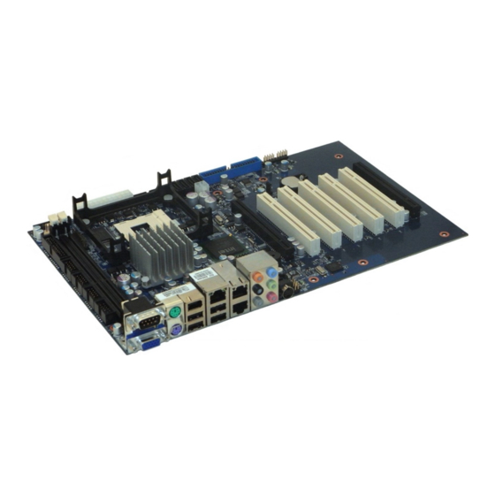
System KTD-N0793-L Page 14 System overview The block diagram below shows the architecture and main components of the KTGM45. The two key ® ® components on the board are the Intel GM45 (Cantiga) and Intel ICH9ME Chipset. Some components (PCI Slots, PCI Express and miniPCI Express) are optional depending on board type. KTGM45 Users Guide... -
Page 15: Processor Support Table
CPU’s are indicated by text. Some processors in the list are distributed from Kontron, those CPU’s are marked by an * (asterisk). However please notice that this marking is only guide line and maybe not fully updated. Clock Cache sSpec no. -
Page 16: System Memory Support
PC3-8500 1066 1066 8533 Notes: Kontron offers the following memory modules: • P/N 1028-6891, DDR3-RAM, 1GB, 240p, 1066MHZ, PC3-8500, DIMM • P/N 1030-5722, DDR3-RAM, 1GB, 240p, 1333MHZ, PC3-10600, DIMM • P/N 1030-5747, DDR3-RAM, 2GB, 240p, 1066MHZ, PC3-8500, DIMM • P/N 1028-6892, DDR3-RAM, 2GB, 240p, 1333MHZ, PC3-10600, DIMM •... - Page 17 KTD-N0793-L Page 17 System Ch. B, DDR3 (SLOT 0) Ch. A, DDR3 (SLOT 1) ** ** Note: Regardless of the memory configuration used (Dual Channel, Single Channel or Flex) the SLOT 1 must always be populated. This is a requirement of the Intel® Management Engine. The below tables shows examples of possible Memory slot configurations for the support of the various Memory modes.
-
Page 18: Ktgm45 Graphics Subsystem
System KTD-N0793-L Page 18 KTGM45 Graphics Subsystem The KTGM45 use the Intel GM45 chipset for the graphical control. This chipset contains two separate, mutually exclusive graphics options. Either the Intel® GMA 4500MHD graphics engine (contained within the GM45 GMCH) is used, or a PCI Express x16 add-in card can be used. When a PCI Expressx16 add-in card is installed, the GMA 4500MHD graphics controller is disabled. -
Page 19: Dvmt 5.0 Support
• TMDS for DVI 1.0 • Display Port • HDMI support Currently available Kontron PCIe Passive Graphic cards: • P/N 820977, KT-PCIe-DVI-HDMI-I, (HDMI, and DVI with TMDS option). Please visit the Kontron website (www.kontron.com ) for details. KTGM45 Users Guide... -
Page 20: Power Consumption
1. Low Power Setup: 2.0GHz (Celeron 575) & 1x 1GB Samsung 2Rx8 PC3-10600U-09-00-A0 DDR3 Ram High Power Setup: 2.53GHz (T9400) Core Duo & 2x 2GB Samsung 2Rx8 PC3-10600U-09-00-A0 DDR3 Ram 2. 12V active cooler (Kontron PN 823132). 3. USB Keyboard/Mouse (Logitech Corded Media Keyboard / Logitech First/Pilot Wheel MSE) 4. TFT (Samsung SyncMaster 953bw) 5. - Page 21 System KTD-N0793-L Page 21 Low Power Setup (Celeron 575 + 1GB RAM) results: DOS Idle, Mean, No external load Supply Current draw Power consumption +12V 1.82A 21.84W 0.295A 1.475W +3V3 1.4A 4.62W -12V 5VSB Total 27.935W +12V only 2.7A 32.4W Windows XP, mean 3DMARK2001 (Game 1 –...
- Page 22 System KTD-N0793-L Page 22 High Power Setup (Core 2 Duo Mobile T9400 + 1GB RAM) results: DOS Idle, Mean, No external load Supply Current draw Power consumption +12V 1.87A 22.44W 0.297A 1.485W +3V3 1.38A 4.554W -12V 5VSB Total 28.479W +12V only 2.76A 33.12W Windows XP, mean...
-
Page 23: Connector Definitions
KTD-N0793-L Page 23 Connector Connector Definitions The following sections provide pin definitions and detailed description of all on-board connectors. The connector definitions follow the following notation: Column Description name Shows the pin-numbers in the connector. The graphical layout of the connector definition tables is made similar to the physical connectors. -
Page 24: Connector Layout
Connector KTD-N0793-L Page 24 Connector layout 3.1.1 KTGM45/mITX Mini-PCIe (backside CF on backside of KTGM45/mITX Plus only of KTGM45/mITX) System temperature sensor (Q19) FEATURE (See note) ATX+12V DDR3 SLOT 0 DDR3 SLOT 1 ATX/ BTXPWR USB8 FRONTPNL USB9 USB10 USB11... -
Page 25: Ktgm45/Flex
KBDMSE AUDIO_HEAD CDROM IEEE1394_0 3.1.3 KTGM45 - IO Bracket area ETHER1 TV-OUT (Not mounted when PN >xxxxxx02) USB2 USB0 AUDIO STACK COM1 IEEE1394_1 * ETHER2 * USB5 * = Not available on KTGM45/mITX Basic. ETHER3 * USB4 KTGM45 Users Guide... -
Page 26: Ktgm45/Atxe
Connector KTD-N0793-L Page 26 3.1.4 KTGM45/ATXE (See note) FAN_CPU FAN_SYS ATX/ BTXPWR ATX+12V USB10 USB8 FEATURE LVDS USB11 IDE_P USB9 DDR3 SLOT 0 ClrCMOS Jumper DDR3 SLOT 1 FRONTPNL PCI SLOT 0 COM4 PCI SLOT 1 COM3 PCI SLOT 2 COM2 PCI SLOT 3 USB6... -
Page 27: Power Connector (Atx/Btxpwr)
+12V. Use of BTX supply is not required for operation, but may be required to drive high-power PCIe cards. In case of the KTGM45/mITX or in case of other versions of KTGM45 where the total power load from PCI and PCIe slots are limited to one full load for each type of connector, then the ATX/BTXPWR connector can be unconnected, so that the ATX+12V is the only voltage (12V +/-5%) supplied. -
Page 28: Keyboard And Mouse Connectors
KTD-N0793-L Page 28 Connector Keyboard and Mouse connectors Attachment of a keyboard or PS/2 mouse adapter can be done through the stacked PS/2 mouse and keyboard connector (MSE & KBD). Both interfaces utilize open-drain signalling with on-board pull-up. The PS/2 mouse and keyboard is supplied from SB5V when in standby mode in order to enable keyboard or mouse activity to bring the system out from power saving states. -
Page 29: Display Connector
KTD-N0793-L Page 29 Connector Display connector The KTGM45 family provides on-board Analogue CRT interface, on-board LVDS panel interface and on- board TV-Out, however the TV-out connector is not mounted. Additionally there is support for ADD2 card (or similar) through the on-board PCI Express x16 connector, with extension capability for support of dual DVI, dual LVDS, VGA and HDMI + DVI. -
Page 30: Lvds Flat Panel Connector (Lvds)
KTD-N0793-L Page 30 Connector 3.4.2 LVDS Flat Panel Connector (LVDS) Note Type Signal Signal Type Note Max. 0.5A +12V +12V PWR Max. 0.5A Max. 0.5A +12V +12V PWR Max. 0.5A Max. 0.5A +12V PWR Max. 0.5A Max. 0.5A PWR Max. 0.5A Max. -
Page 31: Tv-Out
KTD-N0793-L Page 31 Connector Connector 3.4.3 TV-Out The KTGM45 boards include layout for TV-Out connector, but TV-out connector is not mounted from the board PN revision xxxxxx03. Anyway the TV-out has support for (Analogue) Component Video (S-Video, YPbPr or RGB) and Composite Video Output (NTSC/ PAL output format). Pull Pull Note... -
Page 32: Firewire/Ieee1394 Connectors
Firewire/IEEE1394 connectors The KTGM45 support two IEEE Std 1394a-2000 fully compliant cable ports at 100M bits/s, 200M bits/s and 400M bits/s. (Not available on KTGM45/mITX Basic) 3.5.1 IEEE1394 connector (IEEE1304_1) The pinout of the connector IEEE1394_1 (stacked together with USB Ports 4 and 5) is as follows:... -
Page 33: Pci-Express Connectors
Page 33 PCI-Express connectors The KTGM45/mITX supports one (x16) (16-lane) PCI Express port and one miniPCI Express port. KTGM45/Flex and KTGM45/ATXE supports one PCIe x16 port and one PCIe x1 port (in a x16 connector). The 16-lane (x16) PCI Express (PCIe 2.0) port can be used for external PCI Express graphics card. It is located nearest the CPU. - Page 34 KTD-N0793-L Page 34 Connector PEG_RXN[11] PEG_TXP[10]/SDVOC_GREEN PEG_TXN[10]/SDVOC_GREEN# PEG_RXP[10]/SDVOC_INT PEG_RXN[10]/SDVOC_INT# PEG_TXP[9]/SDVOC_BLUE PEG_TXN[9]/SDVOC_BLUE# PEG_RXP[9] PEG_RXN[9] PEG_TXP[8]/SDVOC_CLKN PEG_TXN[8]/SDVOC_CLKP PEG_RXP[8] PRSNT#2 PEG_RXN[8] PEG_TXP[7] PEG_TXN[7] PEG_RXP[7] PEG_RXN[7] PEG_TXP[6] PEG_TXN[6] PEG_RXP[6] PEG_RXN[6] PEG_TXP[5] PEG_TXN[5] PEG_RXP[5] PEG_RXN[5] PEG_TXP[4] PEG_TXN[4] PEG_RXP[4] PEG_RXN[4] PEG_TXP[3] PEG_TXN[3] PEG_RXP[3] PEG_RXN[3] PEG_TXP[2] PEG_TXN[2] PEG_RXP[2] PEG_RXN[2] PEG_TXP[1]...
-
Page 35: Minipci-Express
Connector KTD-N0793-L Page 35 3.6.2 miniPCI-Express The KTGM45/mITX supports one miniPCI Express port. Note Type Signal Signal Type Note WAKE# +3V3 +1.5V CLKREQ# PCIE_mini CLK# PCIE_mini CLK W_Disable# RST# PCIE_RXN +3V3 Dual PCIE_RXP +1.5V SMB_CLK PCIE_TXN SMB_DATA PCIE_TXP +1.5V +3V3 Note 1: 4K7 ohm pull-up to 3V3. -
Page 36: Pci-Express X1 Connector (Pcie X16)
KTD-N0793-L Page 36 Connector Connector 3.6.3 PCI-Express x1 Connector (PCIe x16) The KTGM45/Flex and KTGM45/ATXE supports one PCIe x1 in a x16 socket. Note Type Signal Signal Type Note +12V +12V +12V +12V +12V SMB_CLK SMB_DATA +3V3 +3V3 SB3V3 +3V3 WAKE# RST# PCIE_x4 CLK... - Page 37 KTD-N0793-L Page 37 Connector KTGM45 Users Guide...
-
Page 38: Parallel Ata Hard Disk Interface
CD-ROM drives may be attached to the primary controller by means of the 40 pin IDC connector, PATA. On the KTGM45/mITX Plus the parallel ATA hard disk controller is shared between the PATA connector and the CF connector. -
Page 39: Ide Hard Disk Connector (Pata)
KTD-N0793-L Page 39 Connector 3.7.1 IDE Hard Disk Connector (PATA) This connector can be used for connection of two primary IDE drives. Pull Ioh/ Ioh/ Pull Note Type Signal PIN# Signal Type Note RESET_P# DA10 9 10 DA11 11 12 DA12 13 14 DA13... -
Page 40: Compact Flash Connector (Cf)
Connector 3.7.2 Compact Flash Connector (CF) This connector is mounted on the backside of the KTGM45/mITX Plus. The CF socket support DMA/UDMA modules up to UDMA2. Note: If the CF connector is used then only one PATA device is supported and only by use of 40-wire cable (not 80-wire cable). -
Page 41: Serial Ata Hard Disk Interface
KTD-N0793-L Page 41 Connector Serial ATA Hard Disk interface The KTGM45 boards have an integrated SATA Host controller that supports independent DMA operation on four ports and data transfer rates of up to 3.0Gb/s (300MB/s). The SATA controller supports AHCI mode and has integrated RAID functionality with support for RAID modes 0 and 1. -
Page 42: Serial Ports
KTD-N0793-L Page 42 Connector Serial Ports Four RS232 serial ports are available on the KTGM45. The typical definition of the signals in the COM ports is as follows: Signal Description Transmitted Data, sends data to the communications link. The signal is set to the marking state (-12V) on hardware reset when the transmitter is empty or when loop mode operation is initiated. -
Page 43: Ethernet Connectors
Boazman-LM WG82567LM Gigabit PHY with AMT 4.0 support and the two other controllers (ETHER2 & ETHER3) are based on Intel® Hartwell 82574L PCI Express controller. (ETHER2/ETHER3 are not available on KTGM45/mITX Basic). In order to achieve the specified performance of the Ethernet port, Category 5 twisted pair cables must be used with 10/100MB and Category 5E, 6 or 6E with 1Gb LAN networks. -
Page 44: Usb Connectors (Usb)
Connector KTD-N0793-L Page 44 3.11 USB Connectors (USB) The KTGM45 board contains two Enhanced Host Controller Interface (EHCI) host controllers that support USB 2.0 allowing data transfers up to 480Mb/s. The KTGM45 boards also contains Six Universal Host Controller Interface (UHCI Revision 1.1) controllers that support USB full-speed and low-speed signalling. The KTGM45 board supports a total of twelve USB 2.0 ports. -
Page 45: Usb Connector 1/3 (Usb1/3)
KTD-N0793-L Page 45 Connector 3.11.2 USB Connector 1/3 (USB1/3) See Frontpanel Connector (FRONTPNL) description. 3.11.3 USB Connector 4/5 (USB4/5) USB Ports 4 and 5 are mounted together with IEEE1394_1 port. Pull Pull Note Ioh/Iol Type Signal Signal Type Ioh/Iol Note 5V/SB5V /15K 0.25/2... -
Page 46: Usb Connector 8/9 (Usb8/9)
Connector KTD-N0793-L Page 46 3.11.5 USB Connector 8/9 (USB8/9) USB Ports 8 and 9 are supplied on the internal USB8/9 pinrow connector. Pull Pull Note Ioh/Iol Type Signal Signal Type Ioh/Iol Note PWR 5V/SB5V 5V/SB5V PWR USB8- USB9- USB8+ USB9+ 9 10 Note 1: In order to meet the requirements of USB standard, the 5V input supply must be at least 5.00V. -
Page 47: Audio Connectors
KTD-N0793-L Page 47 Connector 3.12 Audio Connectors The on-board Audio circuit implements 7.1+2 Channel High Definition Audio with UAA (Universal Audio Architecture), featuring five 24-bit stereo DACs and three 20-bit stereo ADCs. 3.12.1 Audio Speakers, Line-In, Line-Out and Microphone Audio Speakers, Line-in, Line-out and Microphone are available in the stacked audiojack connector. Below is shown audio stack configuration when configured for 8-channel audio. -
Page 48: Cdrom Audio Input (Cdrom)
Connector KTD-N0793-L Page 48 3.12.2 CDROM Audio Input (CDROM) CD-ROM audio input may be connected to this connector. It may also be used as a secondary line-in signal. Pull Signal Type Ioh/Iol Note CD_Left CD_GND CD_GND CD_Right Note 1: The definition of which pins are use for the Left and Right channels is not a worldwide accepted standard. -
Page 49: Audio Header (Audio_Head)
KTD-N0793-L Page 49 Connector 3.12.4 Audio Header (AUDIO_HEAD) Pull Ioh/ Ioh/ Pull Note Type Signal Signal Type Note LFE-OUT CEN-OUT AAGND AAGND FRONT-OUT-L FRONT-OUT-R AAGND AAGND REAR-OUT-L 9 10 REAR-OUT-R SIDE-OUT-L 11 12 SIDE-OUT-R AAGND 13 14 AAGND MIC1-L 15 16 MIC1-R AAGND 17 18... -
Page 50: Fan Connector (Fan_Cpu)
KTD-N0793-L Page 50 Connector 3.13 Fan Connector (FAN_CPU) The FAN_CPU is used for the connection of the FAN for the CPU. The FAN_SYS can be used to power, control and monitor a fan for chassis ventilation etc. The 4pin header is recommended to be used for driving 4-wire type Fan in order to implement FAN speed control. -
Page 51: Clear Cmos Jumper (J13)
KTD-N0793-L Page 51 Connector 3.14 Clear CMOS Jumper (J13) The Clear-CMOS Jumper (J13) is used to clear the CMOS content. J13 (in default position) KTGM45/mITX KTGM45/ATXE KTGM45/Flex pin1-2 pin2-3 Description Default positions Clear CMOS data * Secure CMOS function is disabled and Default values are used WARNING: Don’t leave the jumper in this position, otherwise if power is disconnected the battery will fully... -
Page 52: Tpm Connector (Tpm)
3.15 TPM Connector (TPM) This TPM connector (not available on KTGM45/mITX) is in general unsupported. TPM is already included in the KTGM45 so TPM connector is not needed, however in special projects LPC interface might be of interest and then TMP connector is required. -
Page 53: Front Panel Connector (Frontpnl)
KTD-N0793-L Page 53 Connector 3.17 Front Panel Connector (FRONTPNL) Pull Ioh/ Ioh/ Pull Note Type Signal Signal Type Note USB10/11_5V USB10/11_5V USB1- USB3- USB1+ USB3+ 9 10 LINE2-IN-L 11 12 HD_LED 13 14 SUS_LED 15 16 PWRBTN_IN# RSTIN# 17 18 SB3V3 19 20 LINE2-IN-R... -
Page 54: Feature Connector (Feature)
KTD-N0793-L Page 54 Connector 3.18 Feature Connector (FEATURE) Pull Ioh/ Ioh/ Pull Note Type Signal Signal Type Note INTRUDER# EXT_SMI# PWR_OK SB5V SB3V3 EXT_BAT PWR 9 10 4K7/ /12mA IOT GPIO0 11 12 GPIO1 /12mA 4K7/ 4K7/ /12mA IOT GPIO2 13 14 GPIO3 /12mA 4K7/... -
Page 55: Pci Slot Connector (Pci Slot)
KTD-N0793-L Page 55 Connector 3.19 PCI Slot Connector (PCI Slot) Terminal Note Type Signal Signal Type Note -12V TRST# +12V INTA# INTB# INTC# INTD# +5V (I/O) PWR GNT3# RST# CLKB +5V (I/O) PWR GNT0# REQ0# PWR +5V (I/O) PME# AD31 AD30 AD29 +3.3V... -
Page 56: Signal Description - Pci Slot Connector
Connector KTD-N0793-L Page 56 3.19.1 Signal Description – PCI Slot Connector SYSTEM PINS Clock provides timing for all transactions on PCI and is an input to every PCI device. All other PCI signals, except RST#, INTA#, INTB#, INTC#, and INTD#, are sampled on the risingedge of CLK and all other timing parameters are defined with respect to this edge. -
Page 57: Ktgm45 Pci Irq & Int Routing
Interrupt D is used to request an interrupt and only has meaning on a multi-function device. INTD# 3.19.2 KTGM45 PCI IRQ & INT routing Board type Slot IDSEL INTA INTB INTC INTD KTGM45/mITX REQ0# GNT0# AD16 INT_PIRQ#A INT_PIRQ#B INT_PIRQ#C INT_PIRQ#D KTGM45/Flex REQ0# GNT0# AD16 INT_PIRQ#A INT_PIRQ#B INT_PIRQ#C INT_PIRQ#D REQ1# GNT1# AD17 INT_PIRQ#E INT_PIRQ#F INT_PIRQ#G INT_PIRQ#H... -
Page 58: On-Board - & Mating Connectors
KBDMSE Molex 22-23-2061 Molex 22-01-2065 CDROM Foxconn HF1104E Molex 50-57-9404 Molex 70543-0038 SATA Hon Hai LD1807V-S52T Molex 67489-8005 Kontron KT 821035 (cable kit) ATXPWR Molex 44206-0002 Molex 5557-24R ATX+12V-4pin Lotes ABA-POW-003-K02 Molex 39-01-2045 LVDS Don Connex C44-40BSB1-G Don Connex A32-40-C-G-B-1... -
Page 59: System Resources
System Resources KTD-N0793-L Page 59 System Resources Memory Map Address (hex) Size Description 00000000 0009FFFF 655360 System board 000A0000 000BFFFF 131072 PCI-bus 000A0000 000BFFFF 131072 Mobile Intel(R) 4 Series Express Chipset Family 000C0000 000CFFFF 65536 System board 000D0000 000DFFFF 65536 PCI-bus 000E0000 000FFFFF... -
Page 60: Pci Devices
KTD-N0793-L Page 60 System Resources System Resources PCI Devices Device Function Vendor Device Chip Device Function 8086 2A40 GM45 Chipset Host Bridge 8086 2A42 GM45 Chipset VGA Controller 8086 2A43 GM45 Chipset VGA Controller 8086 2A44 GM45 Chipset Management Engine 8086 10F5 82567LM LAN... -
Page 61: Interrupt Usage
KTD-N0793-L Page 61 System Resources Interrupt Usage Notes IRQ0 IRQ1 IRQ2 IRQ3 IRQ4 IRQ5 IRQ6 IRQ7 IRQ8 IRQ9 IRQ10 IRQ11 IRQ12 IRQ13 IRQ14 IRQ15 IRQ16 IRQ17 IRQ18 IRQ19 IRQ20 IRQ21 IRQ22 IRQ23 IRQ24 IRQ25 IRQ26 KTGM45 Users Guide... -
Page 62: Io Map
System Resources KTD-N0793-L Page 62 IO Map Address range (hex) Size Description DMA-controller 3320 PCI-bus Motherboard resources Programmable interrupt controller Motherboard resources System timer Motherboard resources Standard keyboard System Speaker Motherboard resources Standard keyboard Motherboard resources System CMOS/Real time clock Motherboard resources Motherboard resources DMA-controller... - Page 63 KTD-N0793-L Page 63 System Resources B000 B00F Intel(R) ICH9M/M-E 2 port Serial ATA Storage Controller 2 - 292D B080 B08F Intel(R) ICH9M/M-E 2 port Serial ATA Storage Controller 2 - 292D B400 B403 Intel(R) ICH9M/M-E 2 port Serial ATA Storage Controller 2 - 292D B480 B487 Intel(R) ICH9M/M-E 2 port Serial ATA Storage Controller 2 - 292D...
-
Page 64: Bios
Enabled and follow the operating system’s installation instructions. BIOS Update The BIOS can be updated using Kontron utility called bf.exe, which are available on the Kontron Web site. The utility supports DOS and Windows environment. Before updating the BIOS, AMT related restrictions must be followed. -
Page 65: Bios Setup
KTD-N0793-L Page 65 BIOS setup BIOS setup Introduction The BIOS Setup is used to view and configure BIOS settings for the KTGM45 board. The BIOS Setup is accessed by pressing the DEL key after the Power-On Self-Test (POST) memory test begins and before the operating system boot begins. -
Page 66: Advanced Menu
KTD-N0793-L Page 66 BIOS setup Advanced Menu BIOS SETUP UTILITY Main Advanced PCIPnP Boot Security Chipset Exit Advanced Settings Configure CPU. Warning: Setting wrong values in below sections may cause system to malfunction. ► CPU Configuration ► IDE Configuration ► LAN Configuration ►... -
Page 67: Advanced Settings - Cpu Configuration
KTD-N0793-L Page 67 BIOS setup 7.3.1 Advanced settings – CPU Configuration BIOS SETUP UTILITY Advanced CPU Configure For UP platforms leave it Module Version: 3F.15 enabled. For DP/MP servers, it may use to tune performance to the Manufacturer:Intel specific application. Celeron™... -
Page 68: Advanced Settings - Ide Configuration
KTD-N0793-L Page 68 BIOS setup 7.3.2 Advanced settings – IDE Configuration BIOS SETUP UTILITY Advanced IDE Configuration Options Disabled Compatible Mirrored IDER Configuration [Disabled] Enhanced SATA#1 Configuration [Compatible] Configure SATA#1 as [IDE] SATA#2 Configuration [Enhanced] ► Primary IDE Master : [Hard Disk] ►... - Page 69 KTD-N0793-L Page 69 BIOS setup BIOS SETUP UTILITY Advanced Primary IDE Master elect the type of devices connected to the system Device :Hard Disk Vendor :ST340014A Size :40.0GB LBA Mode :Supported Block Mode :16Sectors PIO Mode Async DMA :MultiWord DMA-2 Ultra DMA :Ultra DMA-5 S.M.A.R.T.
- Page 70 KTD-N0793-L Page 70 BIOS setup Feature Options Description Disabled Hot Plug (Only available if SATA#1 is RAID or AHCI) Enabled BIOS SETUP UTILITY Advanced AHCI Settings Enables for supporting AHCI controller operates in AHCI mode during BIOS AHCI BIOS Support [Enabled] control otherwise ►...
- Page 71 KTD-N0793-L Page 71 BIOS setup Feature Options Description Hard Disk Write Protect Disabled Disable/Enable device write protection. This will be Enabled effective only if device is accessed through BIOS IDE Detect Time Out (Sec) Select the timeout value for detecting ATA/ATAPI device(s) ATA(PI) 80Pin Cable Host &...
-
Page 72: Advanced Settings - Lan Configuration
KTD-N0793-L Page 72 BIOS setup 7.3.3 Advanced settings – LAN Configuration BIOS SETUP UTILITY Advanced LAN Configuration Control of Ethernet Devices and PXE boot ETH1 Configuration [Enabled] GbE Wake Up From S5 [Disabled] MAC Address & Link status : 00E0F41E24A4 + ETH2 Configuration (Lower) [Enabled] MAC Address &... -
Page 73: Advanced Settings - Configure Win627Dhg Super Io Chipset
KTD-N0793-L Page 73 BIOS setup 7.3.4 Advanced settings – Configure Win627DHG Super IO Chipset BIOS SETUP UTILITY Advanced Configure Win627DHG Super IO Chipset Allows BIOS to Select Serial Port1 Base Addresses. Serial Port1 Address [3F8/IRQ4] Serial Port2 Address [2F8/IRQ3] Serial Port2 Mode [Normal] Serial Port3 Address [Disabled]... -
Page 74: Advanced Settings - Hardware Health Configuration
KTD-N0793-L Page 74 BIOS setup 7.3.5 Advanced settings – Hardware Health Configuration BIOS SETUP UTILITY Advanced Hardware Health Configuration Disable = Full Speed Thermal: Does regulate System Temperature :48ºC/118ºF fan speed according to CPU Temperature :56ºC/132ºF specified temperature VTIN Temperature :N/A System Temperature 2 :40.50ºC/104ºF... -
Page 75: Advanced Settings - Voltage Monitor
KTD-N0793-L Page 75 BIOS setup 7.3.6 Advanced settings – Voltage Monitor BIOS SETUP UTILITY Advanced Voltage Monitor Requested Core CPU :1.0875 V CPU Vccp :1.072 V AVCC :3.168 V 3VCC :3.168 V P12V :11.800 V :5.016 V P1V05 :1.024 V P1V5 :1.456 V :3.186 V... -
Page 76: Advanced Settings - Acpi Settings
KTD-N0793-L Page 76 BIOS setup 7.3.7 Advanced settings – ACPI Settings BIOS SETUP UTILITY Advanced ACPI Settings General ACPI Configuration settings ► General ACPI Configuration ACPI Version Features [ACPI v1.0] PS/2 Kbd/Mouse S4/S5 Wake [Disabled] Keyboard Wake Hotkey [Any key] USB Device Wakeup From S3/S4 [Disabled] <->... - Page 77 KTD-N0793-L Page 77 BIOS setup Feature Options Description ACPI v1.0 ACPI Version Features Enabled RSDP pointers to 64-bit Fixed System ACPI v2.0 Description Tabled. Different ACPI version has some ACPI v3.0 addition. Disabled PS/2 Kbd/Mouse S4/S5 Wake Enabled: The System can also be waked from S4 or Enabled Disabled: PS/2 Kbd or Mouse can still wake system from S3...
-
Page 78: Advanced Settings - Intel Amt Configuration
KTD-N0793-L Page 78 BIOS setup 7.3.8 Advanced settings – Intel AMT Configuration BIOS SETUP UTILITY Advanced Configuration Intel AMT Parameters Options Disabled Enabled Intel AMT Support [Enabled] Force IDER [Disabled] Force SOL [Disabled] Unconfigure AMT/ME [Disabled] <-> Select Screen Select Item change option General Help BIOS... -
Page 79: Advanced Settings - Intel Txt(Lt) Configuration
KTD-N0793-L Page 79 BIOS setup 7.3.9 Advanced settings – Intel TXT(LT) Configuration BIOS SETUP UTILITY Advanced Configure Intel TXT(LT) Parameters Options Disabled Enabled Intel TXT Initialization [Enabled] BIOS AC[SCLEAN] [Enabled] BIOS AC[SCHECK] [Enabled] Lock DPR [Enabled] Reset TPM Establishment Flag [Enabled] <->... -
Page 80: Advanced Settings - Pci Express Configuration
KTD-N0793-L Page 80 BIOS setup 7.3.11 Advanced settings – PCI Express Configuration BIOS SETUP UTILITY Advanced PCI Express Configuration Enabled/Disabled PCI Express L0s and L1 link power states. Active State Power Management [Disabled] <-> Select Screen Select Item change option General Help BIOS Save and Exit... -
Page 81: Advanced Settings - Remote Access Configuration
KTD-N0793-L Page 81 BIOS setup 7.3.12 Advanced settings – Remote Access Configuration BIOS SETUP UTILITY Advanced Configure Remote Access type and parameters Select Remote Access type. Remote Access [Enabled] Serial port number [COM1] Base Address, IRQ [3F8h, 4] Serial Port Mode [115200 8,n,1] Flow Control [None]... -
Page 82: Advanced Settings - Trusted Computing
KTD-N0793-L Page 82 BIOS setup 7.3.13 Advanced settings – Trusted Computing BIOS SETUP UTILITY Advanced Trusted Computing Enables/Disable TPM TCG (Tpm 1.1/1.2) Support in Bios TCG/TPM Support [Yes] TPM Enabled/Disabled Status [No State] TPM Owner Status [No State] <-> Select Screen Select Item change option General Help... -
Page 83: Advanced Settings - Usb Configuration
BIOS setup KTD-N0793-L Page 83 7.3.14 Advanced settings – USB Configuration BIOS SETUP UTILITY Advanced USB Configuration Enables support for legacy USB. AUTO option disables if no USB Module Version – 2.24.3-13.4 Devices are connected. USB Devices Enabled : 1 Drive Legacy USB Support [Enabled] USB 2.0 Controller Mode... -
Page 84: Advanced Settings - Usb Mass Storage Device Configuration
KTD-N0793-L Page 84 BIOS setup 7.3.15 Advanced settings – USB Mass Storage Device Configuration BIOS SETUP UTILITY Advanced USB Mass Storage Device Configuration Number of seconds POST waits for the USB mass storage device after USB Mass Storage Reset Delay [20 Sec] start unit command. -
Page 85: Pcipnp Menu
KTD-N0793-L Page 85 BIOS setup PCIpnp Menu BIOS SETUP UTILITY Main Advanced PCIPnP Boot Security Chipset Exit Advanced PCI/PnP Settings No: Lets the BIOS configure all the devices in the system. Warning: Setting wrong values in below sections Yes: Lets the operating May cause system to malfunction. -
Page 86: Boot Menu
KTD-N0793-L Page 86 BIOS setup Boot Menu BIOS SETUP UTILITY Main Advanced PCIPnP Boot Security Chipset Exit Boot Settings Configure Settings during System Boot. ► Boot Settings Configuration ► Boot Device Priority <-> Select Screen Select Item Enter Go to Sub Screen General Help Save and Exit Exit... -
Page 87: Boot - Boot Settings Configuration
KTD-N0793-L Page 87 BIOS setup 7.5.1 Boot – Boot Settings Configuration BIOS SETUP UTILITY Boot Boot Settings Configuration Allows BIOS to skip certain tests while booting in order to Quick Boot [Enabled] decrease boot time. Quiet Boot [Disabled] AddOn ROM Display Mode [Force BIOS] Bootup Num-Lock [On]... - Page 88 KTD-N0793-L Page 88 BIOS setup Feature Options Description Disabled Force boot Device Overrides current boot setting. Device must be in the Primary IDE Master boot priority menu, though. If the device fails to boot, Primary IDE Slave the system will NOT try other devices. Secondary IDE Master Secondary IDE Slave Third IDE Master...
-
Page 89: Boot - Boot Device Priority
KTD-N0793-L Page 89 BIOS setup 7.5.2 Boot – Boot Device Priority BIOS SETUP UTILITY Boot Boot Device Priority Specifies the boot sequence from the available devices. 1st Boot Device [ESS-ST380811AS] A device enclosed in parenthesis has been disabled in the corresponding type menu. -
Page 90: Security Menu
KTD-N0793-L Page 90 BIOS setup Security Menu BIOS SETUP UTILITY Main Advanced PCIPnP Boot Security Chipset Exit Security Settings Install or Change the password. Supervisor Password :Not Installed User Password :Not Installed Change Supervisor Password Change User Password Boot Sector Virus Protection [Disabled] Hard Disk Security <->... - Page 91 KTD-N0793-L Page 91 BIOS setup Supervisor Password protection (setup Supervisor before User) Super- visor BIOS User Access control Full Date&Time * Supervisor PSW CMOS (most) View User Limit None * = also: Quick Boot Quiet Boot Repost Video on S3 Resume Active State Power-Management User Password protection only (no Supervisor Password used) CMOS...
-
Page 92: Chipset Menu
KTD-N0793-L Page 92 BIOS setup Chipset Menu BIOS SETUP UTILITY Main Advanced PCIPnP Boot Security Chipset Exit Advanced Chipset Settings Configures North Bridge features. Warning: Setting wrong values in below sections may cause system to malfunction. ► North Bridge Configuration ►... -
Page 93: Advanced Chipset Settings - North Bridge Chipset Configuration
KTD-N0793-L Page 93 BIOS setup 7.7.1 Advanced Chipset Settings – North Bridge Chipset Configuration BIOS SETUP UTILITY Chipset North Bridge Chipset Configuration ENABLE: Allow remapping of overlapped PCI memory above the total physical Thermal Memory Reference Code(TMRC) memory. TS on DIMM [Disabled] Disable: Do not allow Memory Hole... -
Page 94: Advanced Chipset
KTD-N0793-L Page 94 BIOS setup 7.7.2 Advanced Chipset … – North Br. … – Video Function Configuration BIOS SETUP UTILITY Chipset Video Function Configuration This setting is only available for WinXP DVMT Memory size [256MB] PAVP Mode [Disabled] Boot Display Device [VBIOS-Default] TV Standard [VBIOS-Default]... - Page 95 KTD-N0793-L Page 95 BIOS setup Feature Options Description DVMT Memory size 128MB This setting is only available for WinXP 256MB Maximum DVMT Disabled PAVP Mode GMCH Protected Audio Video Path (PAVP) Lite BIOS support. High Boot Display Device VBIOS-Default Options (see note) VBIOS-Default CRT+TV...
-
Page 96: Advanced Chipset Settings - South Bridge Chipset Configuration
BIOS setup KTD-N0793-L Page 96 7.7.3 Advanced Chipset Settings – South Bridge Chipset Configuration BIOS SETUP UTILITY Chipset South Bridge Chipset Configuration Disabled 2 USB Ports 4 USB Ports USB Functions [8 USB Ports] 6 USB Ports USB 2.0 Controller [Enabled] 8 USB Ports HDA Controller... -
Page 97: Advanced Chipset Settings - Me Subsystem Configuration
BIOS setup KTD-N0793-L Page 97 7.7.4 Advanced Chipset Settings – ME Subsystem Configuration BIOS SETUP UTILITY Chipset ME Subsystem Configuration Disabled Enabled BootBlock HECI Message [Enabled] HECI Message [Enabled] End of Post S5 HECI Message [Enabled] ME HECI configuration ME-HECI [Enabled] <->... -
Page 98: Exit Menu
KTD-N0793-L Page 98 BIOS setup Exit Menu BIOS SETUP UTILITY Main Advanced PCIPnP Boot Security Chipset Exit Exit Options Exit system setup after saving the changes. Save Changes and Exit F10 Key can be used for Discard Changes and Exit this operation. -
Page 99: Ami Bios Beep Codes
KTD-N0793-L Page 99 AMI BIOS Beep Codes AMI BIOS Beep Codes Boot Block Beep Codes: Number of Description Beeps Insert diskette in floppy drive A: ‘AMIBOOT.ROM’ file not found in root directory of diskette in A: Base Memory error Flash Programming successful Floppy read error Keyboard controller BAT command failed No Flash EPROM detected... -
Page 100: Os Setup
Use the Setup.exe files for all relevant drivers. The drivers can be found on KTGM45 Driver CD or they can be downloaded from the homepage http://www.kontron.com/ Please note that if Management Engine Driver is not installed then Windows Device Manager will show yellow exclamation mark on the PCI Communication Controller.
Need help?
Do you have a question about the KTGM45/mITX and is the answer not in the manual?
Questions and answers