Table of Contents
Advertisement
Quick Links
Advertisement
Table of Contents

Related Manuals for Value Hobby Sabre-44 3D Profile


Summary of Contents for Value Hobby Sabre-44 3D Profile
-
Page 1: Instruction Manual
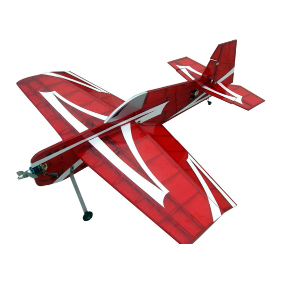
Sabre- - - - 44 44 44 44 3D Profile Sabre 3D Profile Sabre Sabre 3D Profile 3D Profile Almost-Ready-to-Fly Instruction Manual Wingspan: 1100mm (43.31in) Length: 1193mm (46.97in) Wing Area: 40.08 sq dm (621.24sq in) Flying Weight: 1100g-1250g (2.43lb-2.76lb) -
Page 2: Dear Customer
Further, Value Hobby reserves the right to modify this warranty without notice. Value Hobby has no control over the final stages of assembly or the material used for the final assembly. No liability shall be assumed nor materials used for the final user-assembled product. By the act of using the final product the user accepts all resulting liability. -
Page 3: Safety In Flying
Examination Unpack your airplane and examine the components. Check for damage of any kind. If you see any damage, please contact Value Hobby immediately. Covering Your airplane was packed in plastic at the factory without any wrinkles in the covering. You may notice some wrinkles now;... - Page 4 www.valuehobby.com/sabre-44.html RECOMMENDED RADIO EQUIPMENT Product Quantity 4 channel Radio Power HD 1711MG Metal Gear Mini Servo PHD-SV-0366 Servo Universal Servo Y-Harness 12-Inch (Futaba "J" and JR Compatible) AMS-AC-0869 Y-Harness Universal Servo Extension 12-Inch (Futaba "J" and JR Compatible) AMS-AC-0560 Extension RECOMMENDED POWER SETUP Light Power Setup Product...
- Page 5 www.valuehobby.com/sabre-44.html Accessories: Landing Gear Assembly Main landing gear (1 pair) Mounting screws for landing gear---M3*20mm (0.8in) socket head cap screw (2) M3 locknut (2) Main wheel (2) Axle---M4*37mm (1.5in) (2) Wheel collar with grub screw (4) M4 locknut (2) Electric Motor Mount Assembly Motor mount set (1) Mounting screws for motor---M3*15mm (0.6in) socket head cap screw (4) M3 locknut (4)
-
Page 6: Section 1: Landing Gear Installation
Step3. Repeat step1 and step2 to install the Section 1: Landing Gear Installation remaining wheel and axle. Required items: Step4. Pierce the covering on the fuselage for the Fuselage (1) mounting holes for landing gears. Landing gear set (1) Step5. Install the two landing gears to the fuselage using two M3*20mm (0.8in) socket head cap Step1. -
Page 7: Section 2: Main Wing Installation
www.valuehobby.com/sabre-44.html Section 2: Main Wing Installation Required items: Main Wing (1) Step1. Use a hobby knife to remove the coverings for wing opening as shown. Step3. Insert the main wing into the fuselage, and adjust the main wing in the fuselage to make A=A’, B=B’. -
Page 8: Section 3: Aileron Installation
www.valuehobby.com/sabre-44.html Step4. Carefully use a hobby knife to trim the Step6. Slide the wing into the position. covering 1.5mm (0.06in) from inside the lines, both Double-check the alignment as described in step3. on the top and bottom. (Note: Don’t cut into the Allow the epoxy to fully cure before proceeding. -
Page 9: Section 4: Aileron Servo And Linkage Installation
www.valuehobby.com/sabre-44.html Step2. Stature the thin CA to the hinge slot to glue Section 4: Aileron Servo and linkage the hinges to the aileron. Installation Required items: Control Horn (2) Servo (2) (sold separately) Servo arm (2) Ball linkage set (2) Step1. - Page 10 www.valuehobby.com/sabre-44.html Step3. Install the pushrod connector to the servo Step6. Position the servo and use a 1.5mm (0.06in) arm and install the servo arm to the disc servo horn drill bit to drill two holes as shown. as shown. Step7. Use two self-tapping screws to secure the Step4.
-
Page 11: Section 5: Horizontal Stabilizer And Elevator Installation
www.valuehobby.com/sabre-44.html Step9. Thread the aileron servo pushrod to the link ball. Install the ball link set to the control horn. Step2. Insert five hinges into the pre-cut slots in the horizontal stabilizer. Step10. Center the control surface, and tighten the grub screw to secure the pushrod wire to the servo arm. - Page 12 www.valuehobby.com/sabre-44.html Step5. Apply some thin CA to glue the hinges to the Step7. Use a felt-tipped pen to trace the outline of elevator. the fuselage onto the stabilizer, both on the top and bottom. Step6. Slide the stabilizer into the position in the fuselage.
-
Page 13: Section 6: Rudder And Tail Wheel Installation
www.valuehobby.com/sabre-44.html Step9. Apply some epoxy to the exposed wood on Step1. Use a wheel collar to install the tail wheel to the top and bottom of the stabilizer and fuselage. the tail gear wire. Step2. Slide a wheel collar and bracket to the tail gear wire, and bend 90 degree where it is 64mm (2.52in) from the spring. - Page 14 www.valuehobby.com/sabre-44.html Step3. Drill a hole on the rudder to insert the tail Step5. Insert four hinges to the pre-cut slots in the gear wire. rudder. Step6. Apply some thin CA to glue the hinges to the Step4. Fit the wire to the notch in the rudder, and rudder apply some thin CA glue it securely.
-
Page 15: Section 7: Rudder And Elevator Servo & Linkage Installation
www.valuehobby.com/sabre-44.html Step8. Center the rudder and use two self-tapping screws to install the tail wheel gear to the fuselage. Tighten the grub screws on the wheel collar. Step2. Install the elevator servo control horn. Connect the pushrod to the control horn using `````. Step3. -
Page 16: Section 8: Motor & Prop Installation
www.valuehobby.com/sabre-44.html Step5. Locate the slot in the rudder for control horn, Step8. Use the servo pushrod to connect the servo and use a hobby knife to cut through the coverings. and control horn as shown. (Remember to center the control surface before tighten the grub screw). Step6. - Page 17 www.valuehobby.com/sabre-44.html Step2. Assemble the motor mount as shown. And Step5. Use four M3*15mm (0.6in) socket head cap use some epoxy to secure it. screws and four M3 locknuts to install the motor to the motor mount. Step6. Install the prop to the motor. Step3.
-
Page 18: Section 9: Set Up The Cg And Control
www.valuehobby.com/sabre-44.html Set up the control throws as shown: Aileron High Rate Low Rate 70 % 50 % Down 70 % 50 % Elevator High Rate Low Rate 70 % 50 % Down 70 % 50 % Rudder High Rate Low Rate Left 70 % 50 %... - Page 19 www.valuehobby.com 2012/12/09...
Need help?
Do you have a question about the Sabre-44 3D Profile and is the answer not in the manual?
Questions and answers