Table of Contents
Advertisement
Quick Links
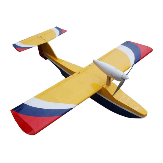
Neptune Seaplane25 ARF
Instruction Manual
Specifications
Wingspan: 1270mm (50in)
Length: 1155mm (45.5in)
Wing Area: 34.8 sq dm (539.4 sq in)
Weight: 1950g (4.30lbs)
Product Highlights
Removable hatch on the fuselage for easy battery
access. Includes high quality hardware.
Classic Neptune trim scheme.
Advertisement
Table of Contents

Related Manuals for Value Hobby Neptune Seaplane25


Summary of Contents for Value Hobby Neptune Seaplane25
-
Page 1: Instruction Manual
Neptune Seaplane25 ARF Instruction Manual Specifications Wingspan: 1270mm (50in) Length: 1155mm (45.5in) Wing Area: 34.8 sq dm (539.4 sq in) Weight: 1950g (4.30lbs) Product Highlights Removable hatch on the fuselage for easy battery access. Includes high quality hardware. Classic Neptune trim scheme. -
Page 2: Dear Customer
This model should be built and flown by an experienced pilot and only flown at AMA sanctioned sites. Value Hobby guarantees this model to be free of defects in materials and workmanship at the date of purchase. This warranty does not cover any parts damaged by use or modifications. In no way shall Value Hobby’s liability exceed the original cost of the purchased model. -
Page 3: Safety In Flying
Examination Unpack your airplane and examine the components. Check for damage of any kind. If you see any damage, please contact Value Hobby immediately. Covering Your airplane was packed in plastic at the factory without any wrinkles in the covering. You may notice some wrinkles now;... - Page 4 www.valuehobby.com/neptune25.html RECOMMENDED RADIO EQUIPMENT Product Quantity Radio 4 channel FLY-RC-1310 Servo Emax ES3104 Metal Gear Mini Servo EMX-SV-2472 Y-Harness Universal Servo Y-Harness 12-Inch (Futaba "J" and JR Compatible) AMS-AC-0869 Extension Universal Servo Extension 12-Inch (Futaba "J" and JR Compatible) AMS-AC-0560 RECOMMENDED POWER SETUP Light Power Setup Product...
- Page 5 www.valuehobby.com/neptune25.html Main Parts and Accessories:...
-
Page 6: Part Lists
www.valuehobby.com/neptune25.html Part Lists: Fuselage x 1 Wing panel x 2 Aileron x 2 Horizontal stabilizer x 1 Elevator x 1 Fin x 1 Rudder x 1 Cowling x 1 M3*12mm (0.5-inch) round head self-tapping screw x 6 for mounting cowling Motor mount x 1 M3*12mm (0.5-inch) screw x 1 for mounting motor mount M3*20mm (0.8-inch) screw x 4 for mounting motor... -
Page 7: Section1: Install The Ailerons And Floats
www.valuehobby.com/neptune25.html Section1: Install the ailerons and floats Step3. Apply some thin CA to glue the aileron to the wing panel. Make sure to glue both the top and bottom. Once the CA has cured, gently pull on Step1. Drill a 3/32-inch hole into the center of each the aileron to make sure the hinges are secure. -
Page 8: Section2: Install The Ailerons Servo & Linkages
www.valuehobby.com/neptune25.html Step4. Connect the aileron servo pushrod Section2: Install the ailerons servo Φ1.8x145mm (5.7-inch) to control horn using & linkages clevis and M2x10mm (0.4-inch) clevis bolt. Step1. Use a hobby knife to remove the covering for inboard servo in the bottom of the wing. Step5. -
Page 9: Section3: Install Fin And Rudder
www.valuehobby.com/neptune25.html Section3: Install fin and rudder Step4. Use thin CA to secure the rudder to the fin. Position the tail skid on the fuselage, and use a felt-tipped pen to trace the outline of the fin. Step1. Position the fin on the fuselage, and use a felt-tipped pen to trace the outline of the fin. -
Page 10: Section4: Install Horizontal Stabilizer And Elevator
www.valuehobby.com/neptune25.html Section4: Install horizontal Section5: Install elevator and stabilizer and elevator rudder servo & linkages Step1. Connect the Elevator pushrod wire Step1. Attach the elevator to horizontal stabilizer Φ1.8x750mm (29.5-inch) to control horn through in the same procedure as installing the aileron in clevis and M2*10mm (0.4-inch) clevis bolt. -
Page 11: Section6: Install Elevator Servo And Linkage (Optional)
www.valuehobby.com/neptune25.html Step4. In the same procedure install the Section6: Install elevator servo control horn onto the rudder. and linkage (optional) We offer another installing method for elevator servo. Step1. Use a hobby knife to remove the coverings for inboard servo. Step5. -
Page 12: Section7: Install Motor And Prop
www.valuehobby.com/neptune25.html Section7: Install motor and prop Step4. With control surface centered, tighten the grub screw. Step1. Prepare a extension cable for connecting the battery and ESC. Step2. As shown thread a 12-inch servo extension and battery-to-ESC cable though the motor mount as shown. - Page 13 www.valuehobby.com/neptune25.html Step3. Remove the coverings for motor mount. Step6. Use four M3*20mm (0.8-inch) screws, four M3 washer and four M3 nut to install the motor to the motor mount. Step4. Insert the motor mount into the fuselage. Step7. Position the cowling in the motor mount. Step5.
-
Page 14: Section8: Install Wing
www.valuehobby.com/neptune25.html Step8. Drill the mounting holes. Section8: Install wing Step1. Use wing joiner and epoxy to join two wing panels together. Step9. Use six M3*12mm (0.5-inch) self-tapping screws to secure the cowling to the motor mount. Step2. Install the wing by aligning the dowels from the wing into the holes in the fuselage. -
Page 15: Section9: Set Up Cg And Control Throws
www.valuehobby.com/neptune25.html Section9: Set up CG and control throws Measure the CG from the leading edge of wing panel. Adjust the battery pack; the CG should be at 25-30% MAC (Mean Airfoil Chord). The CG is 79mm (3.1-inch) from the leading edge of the wing. - Page 16 www.valuehobby.com 2013-1-24...
Need help?
Do you have a question about the Neptune Seaplane25 and is the answer not in the manual?
Questions and answers