
Related Manuals for Value Hobby Sabre-X


Summary of Contents for Value Hobby Sabre-X
-
Page 1: Instruction Manual
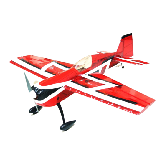
51in Aerobatic Series SabreX Almost-Ready-to-Fly Instruction Manual Specifications Wingspan: 51.2 in (1300mm) Length: 52.3 in (1330mm) Wing Area: 641.7 sq in (41.4sq dm) Flying Weight: 3.75 lb (1700g) - Page 2 At Value Hobby, we want to offer competitive prices, good performance, and products that you can setup and use with ease. That’s why we extensively researched and tested this airplane, and suggested all the products necessary for you to setup properly.
- Page 3 Examination Unpack your airplane and examine the components. Check for damage of any kind. If you see any damage, please contact Value Hobby immediately. Covering Your airplane was packed in plastic at the factory without any wrinkles in the covering. You may notice some wrinkles now;...
-
Page 4: Recommended Setup
Recommended Setup Configuration Model Quantity GForce G15 Brushless Outrunner Motor (3720/2820 Motor TPB-MT-0214 KV850-1100) Speed Control Hobbywing Platinum 60A PRO Brushless ESC with UBEC HWG-SC-0242 FLM-LP-1322 Battery GForce Elite Series 35C 2200mAh 3-4S 11.1V LiPO FLM-LP-1321 Prop 13X6.5 or 14X7 depending on motor and battery selection XYH-MP-0446 servos Power HD 1711MG Metal Gear Mini Servo... - Page 5 ASSEMBLY Step 1: Locate the motor mount and battery mount as shown below. First glue the battery mount onto the fuselage. Next, install the motor mount, and apply epoxy to secure. Step 2: Insert the CA hinges onto the wing. Add CA to secure the hinges and then attach the aileron onto the wing through the hinges.
- Page 6 Step 3: Locate the composite control horn, M2x6mm bolts and matching nuts from the parts bag. You will be using the round servo arm from your servo. Due to differences in the position of bolt opening on different servos, the bolt opening on the control horn may not line up with the opening on your servo arm.
- Page 7 Step 4: Find the landing gear, wheel pants, wheels, M4x35mm bolt and M4 nuts, M4 self-tapping nut, M2x8mm self-tapping screw. Assemble the wheels, landing gear, wheel pants as shown below. When installing the wheel pants, it is recommended that you use 2 M2x8mm self-tapping screws to secure the wheel pants to the landing gear.
- Page 8 Step 5: Find the horizontal stabilizer, two elevator halves, and joiner wire from the parts bag. Use a marker to mark the proper position on the elevator for installing the joiner wire. Use a 3mm (7/64”) drill bit to make the hole. Install the joiner wire on one of the elevator halves, and secure with epoxy (you will install the other elevator half after stabilizer has been install on the fuselage).
- Page 9 Step 6: Remove the covering over the stabilizer opening on the fuselage. Remove the covering on the stabilizer that goes into the fuselage. Make sure the stabilizer is installed in proper position in the fuselage, then secure the stabilizer with CA. Step 7: Install the wing-half with assembled joiner wire into the fuselage, Then attach the other half onto the joiner wire and secure with CA.
- Page 10 Step 8: Remove the covering over the elevator servo opening. Install the composite control horn on the servo and the elevator. Join the elevator servo and the control horn using the M1.8x135mm pushrod. Step 9: Removing the covering where the vertical stabilizer joins with the fuselage. Install the vertical stabilizer on the fuselage and secure with CA.
- Page 11 Step 10: Find the 2 1.8mm easy-connector and control arm as shown below from the parts bag. Assemble the the rudder control arm as shown below. Step 11: Cut the covering over the rudder servo opening on the bottom of the fuselage. Install the rudder servo. Install the composite control arm on the factory servo arm.
- Page 12 Step 12: Assemble the ball-link onto the rudder pushrod. Connect the rudder servo control arm with the control arm on the tail wheel as shown below.
- Page 13 Step 13: Locate the canopy and canopy mount. Use CA to glue the canopy to the mount. To secure the canopy further during flight, use 4 M2x10mm screws, 2 on each side at the position shown in the picture. Step 14: Install the electric motor of your choice on the motor mount. The bolt opening on the mount is for the GForce G15 motor.
- Page 14 Step 15: Adjust the position of the cowling according to the necessary clearance of your motor. Use 4 M2x10mm screw to secure the cowling. Then install the spinner. Step 16: Install the wing using the wing tube, and bolt the wing to secure. Step 17: CG Position is approximately at the wing tube location.
Need help?
Do you have a question about the Sabre-X and is the answer not in the manual?
Questions and answers