
Related Manuals for Value Hobby Cap 35


Summary of Contents for Value Hobby Cap 35
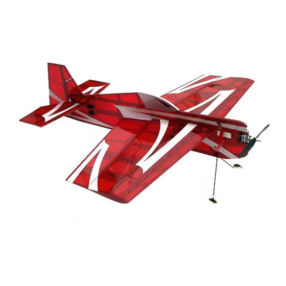
- Page 1 35in Series Electric Profiles Almost-Ready-to-Fly Instruction Manual Cap 35 Sabre 35 Specifications Wingspan: 35in (890mm) Length: 37 in (940mm) Wing Area: Approx. 350 sq in (22.6 sq dm) Flying Weight: Approx. 20oz...
- Page 3 Value Hobby guarantees this model to be free of defects in materials and workmanship at the date of purchase. This warranty does not cover any parts damaged by use or modifications. In no way shall Value Hobby’s liability exceed the original cost of the purchased model.
- Page 4 Never fly too close to yourself or spectators. Never run your motor inside a house or building with the propeller attached – Remove the prop for safety. Required Items CA Glue – Thin and Thick Epoxy glue Hobby Knife Small Phillips Screwdriver Set Metric Allen Wrenches Scissors Small Pliers...
-
Page 5: Recommended Setup
Recommended Setup Configuration Model Radio At least 4 channel Motor GForce E400 Brushless Outrunner Motor (2815-1200KV) TPB-MT-0164 Speed Control Hobbywing Flyfun 30A Brushless ESC HWG-SC-0238 Battery GForce 30C 1300mAh 3S 11.1V LiPO RFI-LP-0293 Prop EMP Neodym 10 X 5 Electric Scimitar Prop XYH-MP-0436 Servos Towerpro MG90S Metal Gear Micro Servo... - Page 6 ASSEMBLY Step 1: Using xacto knife and covering iron, trim the covering over the wing opening, tail stab opening, and motor mount on the fuselage.
- Page 7 Step 2: From the parts bag, find the plywood motor mount parts as shown below. Assemble as shown below and secure with CA glue. The assembly is slightly off-center for the motor offset.
- Page 8 Step 3: From the parts bag, find the wire landing gear, foam wheels, heat shrink tubing, and zip-ties. Secure the wire landing gear using the zip-ties. Secure the foam wheels on the landing gear using heat shrink tubing. Apply a few drops of CA on the heat shrink tubing to further secure the wheels.
- Page 9 Step 4: Slot the wing inside the wing opening on the fuselage. Make sure the wing is in line up properly with the fuselage. Find the plywood control horns and glue them into the pre-cut slots on the aileron.
- Page 10 Step 5: Find the fin, the two elevator halves and the “U” shaped joiner wire. Follow the steps below, test fit the two elevator halves; secure the joiner wire onto the fin and install the fin onto the fuselage; and secure the elevator to the fin. Make sure you have the joiner wire in proper position before gluing the elevators.
- Page 11 Step 6: Use the three CA hinges to secure the rudder to the fuselage. Step 7: Secure the landing skid to the fuselage with the ziptie. Step 8: Make sure all the control surfaces are lined-up properly. A=A` B=B` C=C` D=D`. After everything is properly positioned, apply additional CA glue to secure wing and all control surfaces.
- Page 13 Step 9: Cut the covering over the servo openings and install the servos and connect the control surfaces. For motor and power setup, please refer to the recommended setup.
- Page 14 Step 10: Secure the motor, speed controller and battery. You can arrange the parts to your own preference, but make sure the wires does not interfere with the motor or the servos.
- Page 15 Step 11: Set the CG location at the red dot position as shown below. Control surfaces: Elevator 35-45 degrees Aileron 30-40 degrees Rudder 35-45 degrees...
Need help?
Do you have a question about the Cap 35 and is the answer not in the manual?
Questions and answers